Connected Model Solver

From Mobius Wiki
Revision as of 15:27, 30 October 2014 by Kjkeefe (talk | contribs) (Created page with "== <span style="font-size:120%">Connected Model Solver</span> == The connected model editor makes it possible to define a multi-step solution process that generates results b...")
(diff) ← Older revision | Latest revision (diff) | Newer revision → (diff)
Jump to: navigation, search

Connected Model Solver

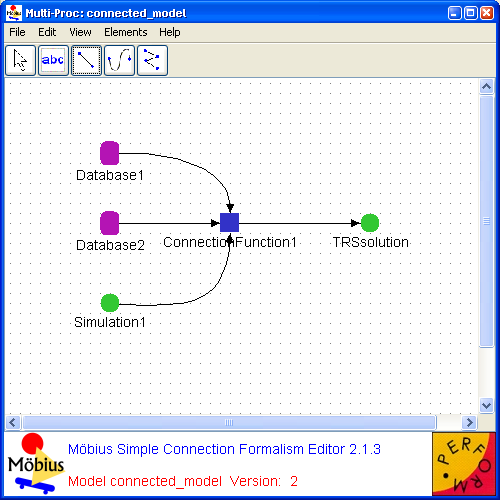
The connected model editor makes it possible to define a multi-step solution process that generates results by solving a series of separate models and passing results between them. Solutions can be generated from either numerical or simulation-based solvers, or even results from other connected model solvers. Solutions can be computed during the run of the connected model solver, or retrieved from precomputed results stored in the database. Results can be combined mathematically by equations and algorithms written in connection functions. An example connected model is shown within the connected model editor in <xr id="fig:conn_editor" />.


<figure id="fig:conn_editor">

Conn editor.png


<xr id="fig:conn_editor" nolink />: An example connected model within the connected model editor.
</figure>


Connected Model Primitives

Connected models are created by graphically representing the solution process as a connected graph of three different types of modeling primitives: solver nodes, database nodes, and connection function nodes. The nodes are connected by directed arcs. When the connected model is solved, each node in the connected graph is processed in turn, receiving results from incoming connections, and passing results to outgoing connections. The output from the final solution step becomes the output of the connected model solver.

The following sections contain descriptions of each of those nodes.


Solver Node     The solver node represents a solution step in the connected model. A solver node can either represent a simulation or a numerical solver. When the connected model is solved, the solver nodes will launch the appropriate solver process. Results that are passed into the solver node override global variable values in the solver node’s child model.

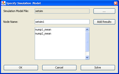
The solver node is defined using a dialog similar to the one shown in <xr id="fig:conn_sim" />. The Simulation Model is selected from the list of available solvers using the ... browse button. The Node Name defaults to a value based on the solver, but can be changed to a more descriptive name.


<figure id="fig:conn_sim">

Conn sim dialog.png


<xr id="fig:conn_sim" nolink />: Solver node specification dialog.
</figure>


The Add Results button is used to specify which results should be exported from this solver node. Results that are exported are displayed in the list at the bottom of the dialog. Users can delete results from the list by selecting them and right-clicking to display a pop-up menu.


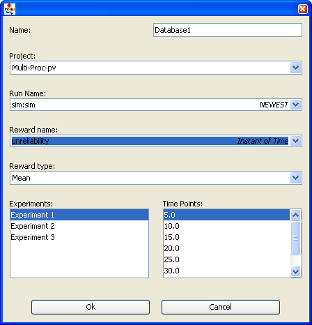
Database Node     The database node specifies a query that extracts previously computed results from the results database. The query is specified using a graphical interface, shown in <xr id="fig:conn_db_dialog" />. The dialog is used to graphically define the result query by ’drilling down’ to the appropriate result. The query is defined top down, by first specifying the name of the project and selecting a particular analysis run. As these fields are identified lower fields in the dialog are populated with available options. The result that will be returned is specifing the desired reward name, reward type (mean, variance, distribution), experiment, and time point.


<figure id="fig:conn_db_dialog">

Conn db dialog.png


<xr id="fig:conn_db_dialog" nolink />: Database query dialog.
</figure>


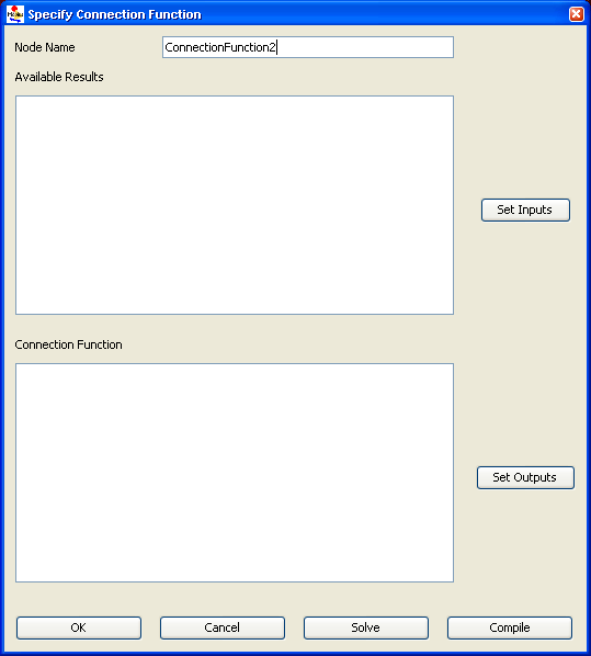
Connection Node     The connection node takes one or more inputs and transforms them to a single output using a custom specified function. The connection function specification dialog is shown in <xr id="fig:conn_conn" />. The Node Name of this dialog specifies the name of this node. The Set Inputs button is used to activate input variables from the list of available input results. Once activated, the variables appear in the Available Results list. Users can remove items from the list by right-clicking on the selected item and choosing Delete from the pop-up menu. The Set Outputs button identifies result names to export from the connection function.


<figure id="fig:conn_conn">

Conn connfunc dialog.png


<xr id="fig:conn_conn" nolink />: Connection function specification dialog.
</figure>


The main feature of the connection node dialog is the Connection Function text area. In this area, Java expressions can be written that map input results to output results. There should be one expression written for each output defined for the connection function node.

The Solve button will execute the function for this connection function node. The Compile button will compile the code written for this connection function, for example, to test the function for syntax correctness.


File Menu

There are two menu items in the File menu which are specific to the connection editor:

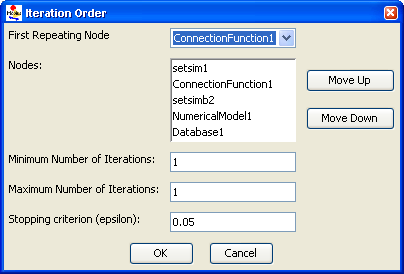
  • The Set iteration order menu displays a dialog that is used to fine-tune the order that nodes of the connected model graph are traversed. An example of the dialog is shown in <xr id="fig:conn_iteration_dialog" />. In many cases it is not necessary to make any adjustments with this dialog. Cases that can require user intervention using this dialog include circular graphs and graphs where there might be an implicit dependency between nodes that is not represented by the connection lines.


<figure id="fig:conn_iteration_dialog">

Conn iteration dialog.png


<xr id="fig:conn_iteration_dialog" nolink />: Connected model iteration dialog.
</figure>


The First Repeating Node option menu defines the starting node of the solution algorithm. The Nodes list specifies the specific order that the solution nodes will be solved. Use the Move Up and Move Down buttons to change the order of selected entries in the Nodes list.
The final three fields are used to contrain the solution process for fixed-point iterations on cyclic graphs. The first two fields specify the minimum and maximum number of iterations. The final field is used to a stopping criterion, in the form of the relative error between the result from the current and previous iterations.
  • The Solve connection model menu is used to launch the connected model solution. Selecting this menu option will immediately execute the first node in the connected model graph and begin the process of solving the connected model. The final results are found in the output files of the last solution step executed by the connected model graph.
Connected Model Solver[edit]

The connected model editor makes it possible to define a multi-step solution process that generates results by solving a series of separate models and passing results between them. Solutions can be generated from either numerical or simulation-based solvers, or even results from other connected model solvers. Solutions can be computed during the run of the connected model solver, or retrieved from precomputed results stored in the database. Results can be combined mathematically by equations and algorithms written in connection functions. An example connected model is shown within the connected model editor in <xr id="fig:conn_editor" />.


<figure id="fig:conn_editor">

Conn editor.png


<xr id="fig:conn_editor" nolink />: An example connected model within the connected model editor.
</figure>


Connected Model Primitives[edit]

Connected models are created by graphically representing the solution process as a connected graph of three different types of modeling primitives: solver nodes, database nodes, and connection function nodes. The nodes are connected by directed arcs. When the connected model is solved, each node in the connected graph is processed in turn, receiving results from incoming connections, and passing results to outgoing connections. The output from the final solution step becomes the output of the connected model solver.

The following sections contain descriptions of each of those nodes.


Solver Node     The solver node represents a solution step in the connected model. A solver node can either represent a simulation or a numerical solver. When the connected model is solved, the solver nodes will launch the appropriate solver process. Results that are passed into the solver node override global variable values in the solver node’s child model.

The solver node is defined using a dialog similar to the one shown in <xr id="fig:conn_sim" />. The Simulation Model is selected from the list of available solvers using the ... browse button. The Node Name defaults to a value based on the solver, but can be changed to a more descriptive name.


<figure id="fig:conn_sim">

Conn sim dialog.png


<xr id="fig:conn_sim" nolink />: Solver node specification dialog.
</figure>


The Add Results button is used to specify which results should be exported from this solver node. Results that are exported are displayed in the list at the bottom of the dialog. Users can delete results from the list by selecting them and right-clicking to display a pop-up menu.


Database Node     The database node specifies a query that extracts previously computed results from the results database. The query is specified using a graphical interface, shown in <xr id="fig:conn_db_dialog" />. The dialog is used to graphically define the result query by ’drilling down’ to the appropriate result. The query is defined top down, by first specifying the name of the project and selecting a particular analysis run. As these fields are identified lower fields in the dialog are populated with available options. The result that will be returned is specifing the desired reward name, reward type (mean, variance, distribution), experiment, and time point.


<figure id="fig:conn_db_dialog">

Conn db dialog.png


<xr id="fig:conn_db_dialog" nolink />: Database query dialog.
</figure>


Connection Node     The connection node takes one or more inputs and transforms them to a single output using a custom specified function. The connection function specification dialog is shown in <xr id="fig:conn_conn" />. The Node Name of this dialog specifies the name of this node. The Set Inputs button is used to activate input variables from the list of available input results. Once activated, the variables appear in the Available Results list. Users can remove items from the list by right-clicking on the selected item and choosing Delete from the pop-up menu. The Set Outputs button identifies result names to export from the connection function.


<figure id="fig:conn_conn">

Conn connfunc dialog.png


<xr id="fig:conn_conn" nolink />: Connection function specification dialog.
</figure>


The main feature of the connection node dialog is the Connection Function text area. In this area, Java expressions can be written that map input results to output results. There should be one expression written for each output defined for the connection function node.

The Solve button will execute the function for this connection function node. The Compile button will compile the code written for this connection function, for example, to test the function for syntax correctness.


File Menu[edit]

There are two menu items in the File menu which are specific to the connection editor:

  • The Set iteration order menu displays a dialog that is used to fine-tune the order that nodes of the connected model graph are traversed. An example of the dialog is shown in <xr id="fig:conn_iteration_dialog" />. In many cases it is not necessary to make any adjustments with this dialog. Cases that can require user intervention using this dialog include circular graphs and graphs where there might be an implicit dependency between nodes that is not represented by the connection lines.


<figure id="fig:conn_iteration_dialog">

Conn iteration dialog.png


<xr id="fig:conn_iteration_dialog" nolink />: Connected model iteration dialog.
</figure>


The First Repeating Node option menu defines the starting node of the solution algorithm. The Nodes list specifies the specific order that the solution nodes will be solved. Use the Move Up and Move Down buttons to change the order of selected entries in the Nodes list.
The final three fields are used to contrain the solution process for fixed-point iterations on cyclic graphs. The first two fields specify the minimum and maximum number of iterations. The final field is used to a stopping criterion, in the form of the relative error between the result from the current and previous iterations.
  • The Solve connection model menu is used to launch the connected model solution. Selecting this menu option will immediately execute the first node in the connected model graph and begin the process of solving the connected model. The final results are found in the output files of the last solution step executed by the connected model graph.