Replicate/Join
Replicate/Join
This section begins with an overview of the Replicate/Join composed model formalism as well as definitions of terms that will be used throughout the section. Then, the different parts of the Replicate/Join composed model formalism and the way they can be used to build a composed model will be described.
Overview
The Replicate/Join composed model formalism was originally conceived for SAN models[1]. However, in the Möbius tool, it can be used with any atomic or composed formalism. The formalism enables the modeler to define a composed model in the form of a tree, in which each leaf node is a predefined submodel node (atomic or composed), and each non-leaf node is classified as either a Join node or a Replicate node. The root of the tree represents the complete composed model.
A Join is a general state-sharing composition node used to compose two or more submodels. A Join node may have other Joins, Replicates, or other submodels defined as its children.
A Replicate is a special case of the Join node used to construct a model consisting of a number of identical copies of a submodel. The resulting composed model is equivalent, in behavior, to that which would result from a Join composed model in which all the children were copies of the same submodel. A Replicate node has one child, which may be another Replicate, a Join, or a single atomic or composed model. The modeler may also specify a set of state variables to be held in common among all replicated instances of the submodel. For each state variable in that set, all state variables with the same name in each of the instances are shared.
Since the instances of a Replicate composed model are indistinguishable, Möbius is able to exploit this structural symmetry and generate a lumped state space. The lumped state space is smaller than the unlumped state space in which symmetries are not present or exploited. Thus, when appropriate, use of a Replicate node instead of a Join node can lead to less time- and space-consuming state-space-based numerical solution. Details of the symmetry-based optimization remain private inside a Replicate/Join model, and the rest of the Möbius tool has no need to know the details of such optimizations. A more detailed description of this optimization is available in [1].
Replicate/Join composed model editor
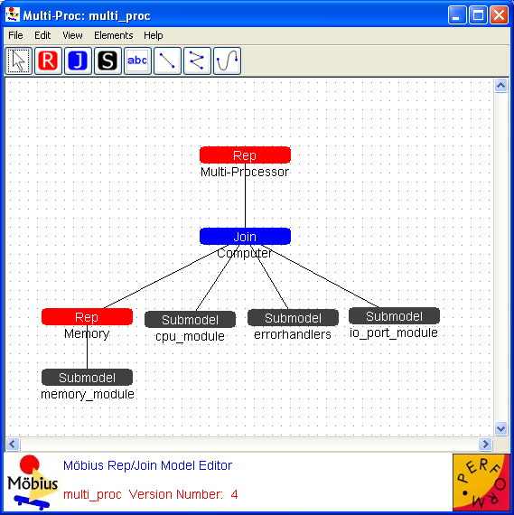
<xr id="fig:repjoin_main_editor" /> shows the Replicate/Join composed model editor. As with other model editors, this editor can be opened either by creating a new model or by opening an existing one. To create a new Replicate/Join, select Composed or any of its children in the project window and select the New command either by choosing it in the context menu or by clicking the leftmost icon in the toolbar (see <xr id="fig:project_main" />). To open an existing Replicate/Join model, select the Open command either by choosing it in the context menu or by clicking the corresponding icon.
<figure id="fig:repjoin_main_editor">
This model editor is divided into the following sections:
- Top menu bar. It consists of the following five menus: File, Edit, View, Elements, and Help.
- Toolbar. It gives the user one-click access to some of the menu commands.
- Editor pane. The composed model is drawn in this area.
- Status pane. The version of Möbius running and the version of the composed model that is open are shown in this pane.
File, Edit, View, and Help menus have sets of commands similar to those in the previously described model editors. For more information on those menus, refer to Section 3.1. The menus unique to the Elements menu in this editor are explained below.
Elements menu
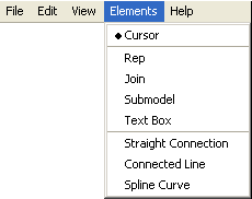
As with other GUI-based model editors, the Elements menu (shown in <xr id="fig:repjoin_elements_menu" />) contains the set of all elements from which a Replicate/Join composed model can be built. The order of the elements from top to bottom is the same as the order of buttons on the toolbar.
<figure id="fig:repjoin_elements_menu">
Submodel node
Submodels are the building blocks for constructing larger models. They are models that have already been built in any of the atomic or composed model editors, and form the leaves of the tree structure of Replicate/Join composed models. To create a Submodel node, first either select Submodel from the Elements menu or click on the ![]() icon in the toolbar. Then click in the editor pane where the node needs to be placed.
icon in the toolbar. Then click in the editor pane where the node needs to be placed.
The set of commands available for a submodel node are available in its context menu (opened by right-clicking on the node) and are Edit, Open, Hide Label (or Show Label), and Delete.
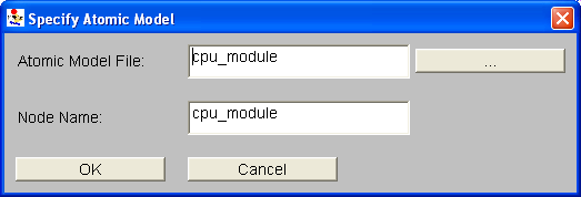
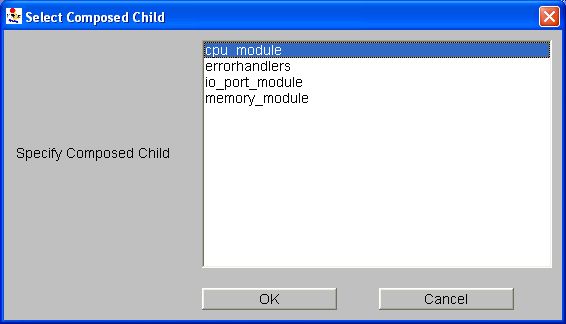
Edit opens the Specify Atomic Model dialog as shown in <xr id="fig:repjoin_submodel_dialog" />. To choose which model to use for this node, click the “...” button, and a list of existing atomic and composed models will be shown as in <xr id="fig:repjoin_submodel_list" />. The name (or label) of the submodel can be set in the Node Name edit box.
<figure id="fig:repjoin_submodel_dialog">
<figure id="fig:repjoin_submodel_list">
If the type of the submodel has been defined, the Open command opens the appropriate model editor for the submodel node while the composed editor is still open. This feature can be used to study the different building blocks, i.e., submodels of the composed model, while the model is being built.
The Hide Label (Show Label) command hides (or shows) the label of the submodel that is shown below the node. Finally, the Delete command deletes the submodel node from the composed model.
Join node
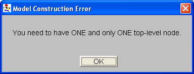
As mentioned before, a Replicate/Join composed model is structurally a tree, and it should be built in a bottom-up fashion. That means that the child(ren) of a Join or Replicate node should be defined before the node itself. Note that this composed editor allows for the definition of only one Replicate/Join tree, corresponding to one top-level (root) node. If there are nodes that are not in any way connected to the rest of the nodes, Möbius will show the error dialog shown in <xr id="fig:repjoin_toplevelerror" />.
<figure id="fig:repjoin_toplevelerror">
A Join node establishes a number of state variable sharings among its children. It must have at least two children. Each sharing consists of a non-empty set of state variables of children of the Join node; no more than one state variable from each child is included. All the state variables in that set are superimposed and given a common name in the Join node. The common name is a state variable in the Join node.
To create a Join node, choose Elements Join or click on the
 ![]() icon in the toolbar and then click in the editor pane where the node needs to be placed. You can access the set of commands available for a Join node by right-clicking on the node: the commands are Edit, Hide Label (or Show Label), and Delete. Hide Label, Show Label, and Delete behave just as they did for submodel nodes.
icon in the toolbar and then click in the editor pane where the node needs to be placed. You can access the set of commands available for a Join node by right-clicking on the node: the commands are Edit, Hide Label (or Show Label), and Delete. Hide Label, Show Label, and Delete behave just as they did for submodel nodes.
After creating a Join node, you must connect it to each of its children by choosing one of the connection lines, Straight Connection ![]() , Connected Line
, Connected Line ![]() , or Spline Curve
, or Spline Curve ![]() , from the Elements menu or the toolbar. A child of a Join node can be another Join, a Replicate, or a submodel node. Note that the first point of the connection between a Join and its child must be the Join node. This direction determines which node is the child and which node is the parent.
, from the Elements menu or the toolbar. A child of a Join node can be another Join, a Replicate, or a submodel node. Note that the first point of the connection between a Join and its child must be the Join node. This direction determines which node is the child and which node is the parent.
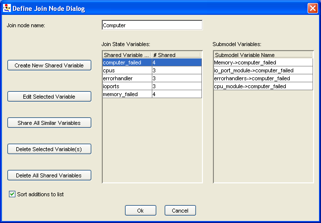
In the next step, use the context-menu command Edit to define the sharings established by the Join node. When you choose Edit, the Define Join Node Dialog shown in <xr id="fig:repjoin_join_dialog" /> appears. On the top of the dialog, the name of the Join node is shown. It can be modified in the Join node name edit box. There are also two lists in this dialog, called Join State Variables and Submodel Variables. The former, as its name implies, shows the state variables of the Join. Each line corresponds to one state variable, which itself corresponds to one sharing. If you highlight a Join state variable in the former list, the latter list shows the set of state variables of the children nodes (i.e., submodels) that are shared to create the Join state variable. For example, in <xr id="fig:repjoin_join_dialog" /> the Join state variable computer_failed is created by sharing 4 state variables among children of the Join node Computer. Notice the arrow symbol that is used to refer to a state variable of a submodel.
<figure id="fig:repjoin_join_dialog">
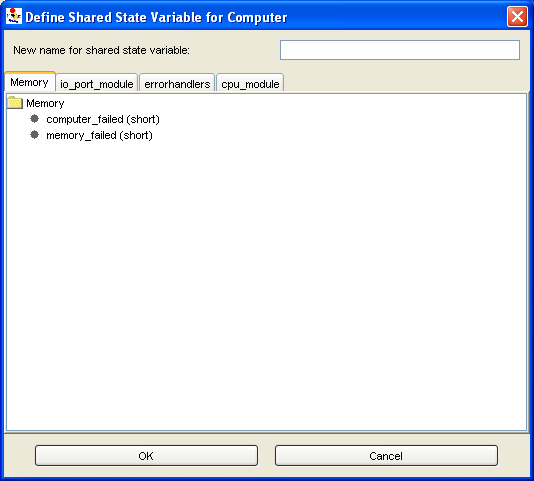
To create or edit an existing Join state variable, click on Create New Shared Variable or Edit Selected Variable, respectively. The Define Shared State Variable dialog, shown in <xr id="fig:repjoin_join_newsv" />, will appear after you press either of the buttons.
<figure id="fig:repjoin_join_newsv">
The main part of the dialog is a multi-tab panel consisting of one tab for each child of the Join node. To define a sharing, select the state variable to be shared in each of the child tabs. No more than one state variable can be selected from each tab. Finally, give the Join state variable a name by entering it in the Join node name edit box. This name will appear in the Join State Variables list (the left list) shown in <xr id="fig:repjoin_join_dialog" />.
Three conditions must be satisfied before a set of state variables can be shared. First, they must all have the same initial value assigned to them in their corresponding model editors. If this condition is not satisfied, Möbius will show the error dialog shown in <xr id="fig:repjoin_join_errors#1" />. Second, they must all be of the same type, regardless of whether it is a simple type, like int, short, or char, or a structural type. An error dialog as shown in <xr id="fig:repjoin_join_errors#2" /> will appear if this condition is not met. Third, none of the state variables can be part of a currently defined sharing relationship.
<figure id="fig:repjoin_join_errors">
<subfigure>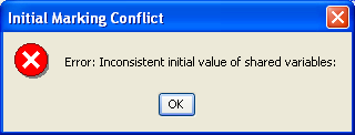 </subfigure> </subfigure>
|
<subfigure>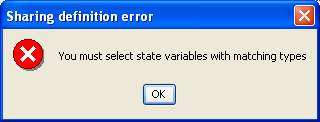 </subfigure> </subfigure>
|
| (a) Nonequal initial values error dialog. | (b) Non-matching types error dialog. |
The Share All Similar Variables button joins all state variables in the children of the Join node with common names. The Join state variable will have the same common name. If you choose the names of submodels’ state variables appropriately with respect to the larger composed model, this feature proves very useful.
Delete Selected Variable(s) deletes the Join state variable selected in the left list. Delete All Shared Variables deletes all the Join state variables. The Sort additions to list checkbox controls how newly created state variables are added to the left list. If it is checked, the name of a new Join state variable will be added to the list in alphabetical order.
Replicate node
This node is a special case of the Join node. Its advantage over the Join node is that it leads to structural symmetries that can eventually result in less time- and space-consuming state-based numerical solution of the model. The extra restrictions that Replicate has relative to Join are as follows:
- All children of a Replicate are of the same submodel type. Therefore, in the composed editor, a Replicate node is connected to only one child node, and the number of replications is specified in the Replicate node definition dialog.
- Only state variables with the same name can be shared among replicas (copies) of a Replicate node. Therefore, to create a Replicate state variable, select only one state variable from the Replicate child; copies of that state variable will be shared among all replicas.
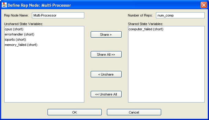
When you choose the Edit command from the context menu of a Replicate node, the Define Rep Node dialog, as shown in <xr id="fig:repjoin_rep_dialog" />, is shown. The label (name) of the Replicate node can be modified in the Rep Node Name edit box. The number of replicas can be set in the Number of Reps edit box. That number can be an integral constant or global variable that has been defined in the current composed model or in any of the constituent atomic or composed models. Two lists of state variables (called Unshared State Variables and Shared State Variables) and a number of buttons between them are used to move state variables from one list to the other.
<figure id="fig:repjoin_rep_dialog">
Each line in the latter (right) list shows the name of a state variable that has been shared among all replicas of the Replicate node. The rest of the state variables of the child submodel are shown in the left list. As mentioned before, each Replicate (or Join) node is itself a model. Notice that in the corresponding model of the Replicate node, for each name in the right list, there is only one copy of that state variable, and for each name in the left list, there are as many copies as have been specified in the Number of Reps edit box, i.e., one copy per child replica.
The buttons between the lists are self-descriptive. Share moves the selected state variable in the left list to the right list and Unshare does the reverse. Share All moves all state variables from the left list to the right list, and Unshare All does the reverse.
