SAN Atomic Formalism
Contents
SAN
Möbius supports multiple formalisms, including stochastic activity networks (SANs). SANs[1] are stochastic extensions to Petri nets[2]. Using graphical primitives, SANs provide a high-level modeling formalism with which detailed performance, dependability, and performability models can be specified relatively easily.
SAN primitives
SANs consist of four primitive objects: places, activities, input gates, and output gates. Activities represent actions of the modeled system. Places represent the state of the modeled system. Input gates are used to control the “enabling” of activities, and output gates are used to change the state of the system when an activity “completes.”
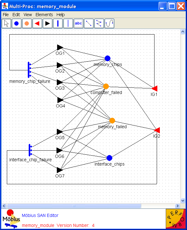
Places Places represent the state of the modeled system. They are represented graphically as circles. In <xr id="fig:atomic_san_editor" />, memory_chips, interface_chips, memory_failed, and computer_failed are places. Each place contains a certain number of tokens, which represents the marking of the place. The set of all place markings represents the marking of the stochastic activity network. Note that tokens in a place are homogeneous, in that only the number of tokens in a place is known; there is no identification of different kinds of tokens within a place.
<figure id="fig:atomic_san_editor">
The meaning of the marking of a place is arbitrary. For example, the number of tokens in a place could represent a number of objects, such as a number of tasks awaiting service. Also, the number of tokens in a place could represent an object of a certain type, such as a task with a certain priority level. This dual nature of a place marking provides a great deal of flexibility in modeling the dynamics of a system.
Activities Activities represent actions in the modeled system that take some specified amount of time to complete. They are of two types: timed and instantaneous. Timed activities have durations that impact the performance of the modeled system, such as a packet transmission time or the time associated with a retransmission timer. Timed activities are represented graphically as thick vertical lines. In <xr id="fig:atomic_san_editor" />, memory_chip_failure and interface_chip_failure are timed activities. Each timed activity has an activity time distribution function associated with its duration. Activity time distribution functions can be generally distributed random variables. Each distribution can depend on the marking of the network. For example, one distribution parameter could be a constant multiplied by the marking of a certain place. Instantaneous activities represent actions that complete immediately when enabled in the system. They are represented graphically as thin vertical lines. No instantaneous activities are represented in <xr id="fig:atomic_san_editor" />. Case probabilities, represented graphically as circles on the right side of an activity, model uncertainty associated with the completion of an activity. Each case stands for a possible outcome, such as a routing choice in a network, or a failure mode in a faulty system. In <xr id="fig:atomic_san_editor" />, activity interface_chip_failure has three cases. Each activity has a probability distribution, called the case distribution, associated with its cases. This distribution can depend on the marking of the network at the moment of completion of an activity. If no circles are shown on an activity, one case is assumed with a probability of one.
An activity is enabled when the predictes of all input gates connected to the activity are true, and all places connected to incoming arcs contain tokens, i.e. have non zero markings. Once enabled, the activity samples its delay distribution function to determine the time delay before the activity fires. When the activity fires it updates the state of the model by subtracting tokens from places connected by incoming arcs, adding tokens to places connected by outgoing arcs, and executing the functions in input and output gates. The specific order that the state updates occur is: input gates, input arcs, output gates, and finally output arcs.
Please be aware that the order in which state updates occur in Möbius differs from UltraSAN. Gates are executed before arcs in Möbius, but the opposite was true in UltraSAN. Also, if there are multiple instances of the same item, for instance multiple input gates, the order of application of the gates is not specified. Models must be constructed so that the gate functions are execution order independent any time there are multiple instances of the same type of gates connected to an activity.
Also associated with each activity is a reactivation function. This function gives marking dependent conditions under which an activity is reactivated. Reactivation of an activated activity means that the activity is aborted and that a new activity time is immediately obtained from the activity time distribution. The reactivation function consists of an activation predicate and a reactivation predicate. An activity will be reactivated at the moment of a marking change if (1) the reactivation predicate holds for the new marking, (2) the activity remains enabled, and (3) the activation predicate holds for the marking in which the activity was originally activated.
Input gates Input gates control the enabling of activities and define the marking changes that will occur when an activity completes. They are represented graphically as triangles. In <xr id="fig:atomic_san_editor" />, IG1 and IG2 are input gates. On the other side of the triangle is a set of arcs to the places upon which the gate depends, also called input places. Each input gate is defined with an enabling predicate and a function. The enabling predicate is a Boolean function that controls whether the connected activity is enabled. It can be any function of the markings of the input places. The input gate function defines the marking changes that occur when the activity completes.
If a place is directly connected to an activity with an arc, it is equivalent to an input gate with a predicate that enables the activity whenever the place has more than zero tokens along with a function that decrements the marking of the place whenever the activity fires.
Output gates Like input gates, output gates define the marking changes that will occur when activities complete. The only difference is that an output gate is associated with a single case. An output gate is represented graphically as a triangle with its flat side connected to an activity or a case. In <xr id="fig:atomic_san_editor" />, OG1, OG2,..., OG6, and OG7 are output gates. On the other side of the triangle is a set of arcs to the places affected by the marking changes. An output gate is defined only with a function. The function defines the marking changes that occur when the activity completes. There is also a default scenario for output gates. If an activity is directly connected to a place, it is equivalent to an activation in which an output gate has a function that increments the marking of the place whenever the activity is fired.
More information on SANs can be found in [1]. The next few sections describe the various features available in the SAN editor to develop a SAN model.
Editor
This section looks into the atomic formalism that represents stochastic activity networks with emphasis on creation, editing, and manipulation of atomic models using the Möbius SAN editor. Refer to Section 2 for details on how to create and open a SAN model.
The names of the selected project and subnet appear in the top left corner (see <xr id="fig:atomic_san_editor" />). The large gridded area in the center is the drawing area . In the case of a new model, this gridded area is blank. Like most applications, the editor lists the menu horizontally at the top of the application’s current active window. If you click on a menu item, it drops a tool panel containing several options. The menu items and tool panel options are used to create and draw in the SAN formalism, as discussed below.
As discussed in Section 3.1, many menus are common to all model editors within Möbius. Please see Section 3.1 for detailed descriptions of the common editor functions. The following paragraphs will discuss the functionality that is unique to the SAN editor.
Edit
Type definitions
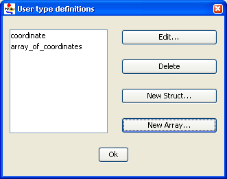
The SAN formalism supports a special element called extended place that allows the model to handle the representation of structures and arrays of primitive data-types. Clicking on Type Editor opens the dialog box shown in <xr id="fig:atomic_san_editor_user_type_definition" />. In this dialog box, you can create new structures and arrays that can be associated with extended places.
<figure id="fig:atomic_san_editor_user_type_definition">
- Use the Edit button to edit any currently defined user-defined types. The GUI can automatically tell if the user is editing an array (see <xr id="fig:atomic_san_editor_user_type_definition_array" />) or structure (see <xr id="fig:atomic_san_editor_user_type_definition_structure" />) and appropriately open the required editor. You are expected to click on the available list of user-defined types to edit them. The editor allows you to change the name of any user-defined type, even if the user-defined type is declared as a field in another user-defined type or associated with an extended place. The interface takes care of updating all the changes.
- Use the Delete button to delete the selected user-defined type that is not being used by any other user-defined type and is not associated with any extended place. If you attempt to delete a type that is in use, an error dialog box pops up. A successful delete removes the user-defined type from the current list.
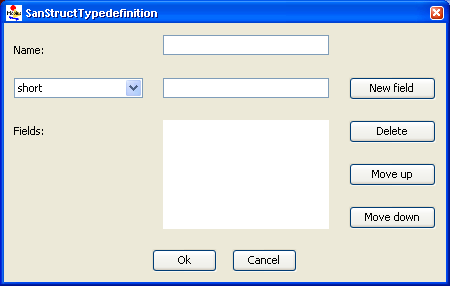
- Use the New Struct button to pop up a new dialog box that allows you to create a new structure-type definition. The pop-up dialog box layout is depicted in <xr id="fig:atomic_san_editor_user_type_definition_structure" />.
<figure id="fig:atomic_san_editor_user_type_definition_structure">
- – Use the Name text box to define a name for the structure.
- – The Fields list shows the fields you declared in the current structure.
- – The New field button adds a new field to the structure. The combo-box on the left lets you choose the type of the field from a list of the standard data types and user-defined data types. Recursive definitions or pointers are not allowed.
- – The Delete button deletes the selected field.
- – The Move up button moves the selected field up by one position.
- – The Move down button moves the selected field down by one position.
- – The OK button accepts all changes made and hides this dialog box, bringing the User-type definitions editor to the front. An error message pops up you try to create a structure with no fields or a structure that has no name or a non-unique name.
- – The Cancel button discards all changes, hides this dialog box and returns you to the User-type definitions editor.
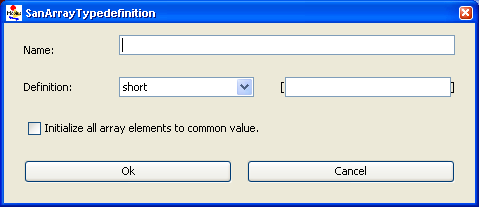
- The New Array button pops up a new dialog box that allows you to create a new array-type definition. The pop-up dialog box layout is depicted in <xr id="fig:atomic_san_editor_user_type_definition_array" />.
<figure id="fig:atomic_san_editor_user_type_definition_array">
- – The Name text box allows you to define a name for the array.
- – The Definition combo-box allows you to select the data type for the array. The choices include primitive data types or user-defined types. You are also expected to declare the size of the array. The elements of the array are generically labeled as index.
- – The Initialize all array elements to common value checkbox makes it easier to manage large arrays. If it is known when the array type is defined that all elements in the array should be initialized to the same value, 0 for instance, clicking this box will avoid the need to initialize each element separately. This option is critical when defining very large arrays because it saves a significant amount of memory within the Möbius editor process.
- – The OK button accepts all changes made, hides this dialog box, and returns you to the User-type definition editor. An error message will pop up if you try to create an array with an invalid size (i.e., a non-numeric, zero, or negative size) or an array that has no name or a non-unique name.
- – The Cancel button discards all changes, hides this dialog box, and brings you back to the User-type definition editor.
- The OK button hides the User type definitions dialog box and brings you back to the SAN editor.
View
Increase size and Decrease size
Click on menu item Increase Size to increase the size of the drawing area. Click on Decrease Size to decrease the size until the scroll bar disappears or becomes equal to area on which the model elements are spread. You can increase the size of the drawing area, scroll down to the extra space created, and add new components to the model, if necessary.
Zoom in and Zoom out
Each time you click on the menu item Zoom In, the GUI enlarges the drawing area by a fixed percentage. The interface takes care of adding scroll bars if necessary so that the entire model can be viewed. To keep the model in focus, be careful not to multiple-click on this option. Zoom Out decreases the size of the model until the scroll bars disappear.
Grid setting
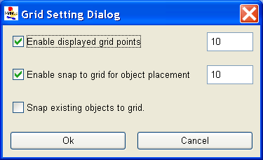
Click on the menu item Grid Setting to open a dialog box as shown in <xr id="fig:atomic_san_editor_grid_setting" />. Here, you can define the X and Y coordinate size of the grid in pixels. Note that if you set the grid to 1 pixel size, it will take an extremely long time to render the model. You can adjust the grid according to your comfort level. There are a few checkboxes on the Grid Setting dialog box. They are Enable display grid points, Enable snap to grid for object placement, and Snap existing objects to grid. Each checkbox is self-explanatory. Use the OK button to accept the changes or the Cancel button to discard the changes. Either way the dialog box will close so that you are returned to the SAN Editor.
<figure id="fig:atomic_san_editor_grid_setting">
Elements
Elements are SAN model primitives. The Elements menu includes the following types of elements:
- Place, which will be represented by a blue circle.
- Extended Place, which will be represented by an orange circle.
- Input Gate, which will be represented by a triangle with its tip pointing to the left.
- Output Gate, which will be represented by a triangle with its tip pointing to the right.
- Instantaneous Activity, which will be represented by a solid vertical bar. If the activity has multiple cases, they appear as small circles on the right side of the vertical bar.
- Timed Activity, which will be represented by a hollow vertical bar. It has small circles on its right side if it has multiple cases.
You can also select a SAN model element by clicking the left button on the required component while the cursor is on the menu item Elements. SAN elements can also be accessed via icons below the menu. To place one of those components, click on it, move it to the desired location, and place it by clicking the left mouse button. A dialog box will appear asking you to specify various attributes relevant to the element type. The name must be unique across the current atomic model. The name also must follow the C++ variable naming convention. The rest of this section discusses various parameters of each model element.
Place
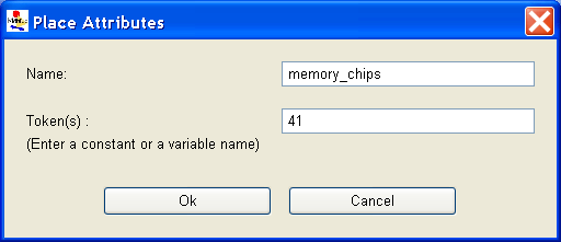
When you create or edit a place (by right-clicking on the place and clicking on Edit in the pop-up window), a dialog box similar to the one shown in <xr id="fig:atomic_san_editor_place_attribute" /> appears.
<figure id="fig:atomic_san_editor_place_attribute">
- The Name text box allows you to modify the name, provided that the new name is unique in the current model.
- The Token(s) text box allows you to edit or modify the initial marking. The value should be a non-negative short integer, which implies that place markings can only be non-negative integers less than or equal to 32,767. However, the initial marking may be defined as a scalar value, or as a global variable. The following points about global initial marking must be noted:
- – global variables for places must be of type short.
- – global variables for initial markings should not be arithmetic expressions, or functions of other initial global markings.
- The OK button accepts the changes and returns you to the SAN Editor. It pops up an error message if there is a problem in validating the tokens text box.
- The Cancel button discards the changes and brings you back to the SAN Editor.
Extended place
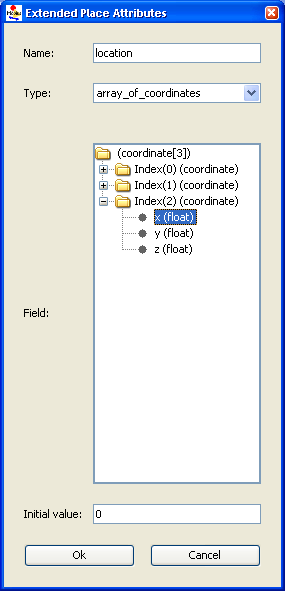
When you create or edit an extended place (by right-clicking on an extended place and clicking on Edit in the pop-up window), a dialog box similar to that shown in <xr id="fig:atomic_san_editor_extended_place_attribute" /> appears.
<figure id="fig:atomic_san_editor_extended_place_attribute">
- The Name text box allows you to modify the name provided that the new name is unique in the current model.
- The Initial value tree represents the current values associated with the structure or array of the extended place. Only the leaf nodes can be initialized to a particular initial value. Clicking on intermediate nodes hides the visible text box. Each time you click on a new leaf node, the GUI evaluates the current initial value for validity, displaying error messages if necessary.
- The text box allows you to edit/modify the initial marking(s) of the selected leaf nodes of the structure or an array. However, the initial marking may be defined as a scalar value, or as a global variable. The following points about global initial marking should be noted:
- – global variables for extended places must be of the same type as the corresponding leaf field.
- – global variables for initial markings should not be arithmetic expressions, or functions of other initial global markings. Note that the current SAN editor only allows global variables of primitive data types.
- The Type combo-box allows you to associate a user-defined type with an extended place. Whenever you change the user-defined type, its values are initialized to 0. The Tree is re-drawn with the new structure or array.
- The OK button accepts the changes and brings you back to the SAN editor. It pops up an error message if there is a problem in validating the tokens text box.
- The Cancel button discards the changes and returns you to the SAN editor.
Input gate
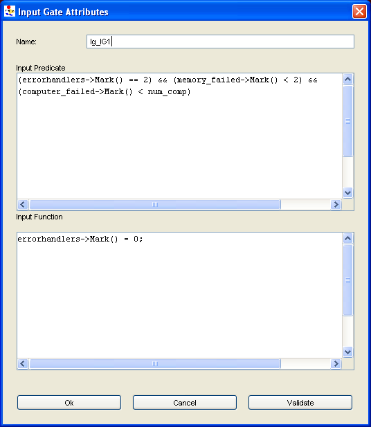
When you create or edit an input gate (by right-clicking on an input gate and clicking on Edit in the pop-up window), a dialog box similar to the one shown in <xr id="fig:atomic_san_editor_input_gate" /> is displayed.
<figure id="fig:atomic_san_editor_input_gate">
When defining an input gate, be aware of the following points:
- You must specify a predicate and a function.
- Input predicates must return a Boolean value. They may be an expression or a sequence of C statements.
- Input functions are sequences of C++ statements.
- No return statements are needed in function specifications, since their action is to change the marking of a SAN, not to return a value.
- If no action is desired in a function (the identity function), this is specified by a lone semicolon.
- Global variables, places, and extended places may be used in defining input gates.
Special note on programming with extended places While defining the function of an input gate or output gate, you can use extended places. You can access the fields of a structure using standard C++ dereferencing of pointers. Consider a scenario in which an extended place “ep” is associated with a user-defined structure called “coordinates” as shown in <xr id="fig:atomic_san_editor_user_type_definition_structure" />, with three fields “x,” “y,” and “id” of types short, short, and char. To access field “x” in any function of a gate, use ep->x->Mark(). In another scenario, extended place “ep” is associated with a user-defined array called “ten_type” that is an array of ten elements of type short. Each of these elements of “ep” can be accessed using the method ep->Index(i)->Mark() where “i” can be a previously defined variable. Remember, it is possible to program user-defined variables with arrays and structures using a similar technique by applying the above-discussed rules recursively.
Output gate
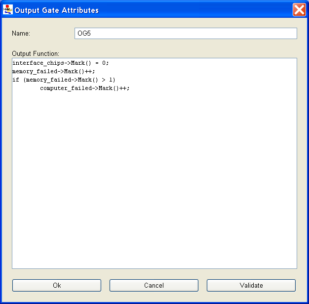
When you create or edit an output gate (by right-clicking on an output gate and clicking on Edit in the pop-up window), a dialog box similar to that shown in <xr id="fig:atomic_san_editor_output_gate" /> appears.
<figure id="fig:atomic_san_editor_output_gate">
Be aware of the following points regarding definition of output gates:
- Only one function is needed.
- Output functions are sequences of C++ statements.
- No return statements are needed in function specifications, since their action is to change the marking of the SAN, not to return a value.
- If no action is desired in a function (the identity function), this is specified by a lone semicolon.
- You may use global variables, places and extended places while defining output gates. Refer to comments in the previous section on programming with extended places.
Activity
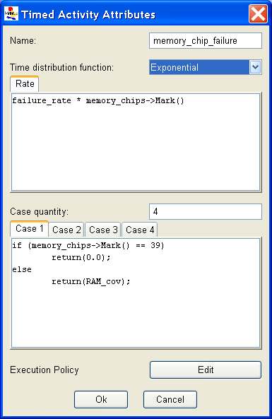
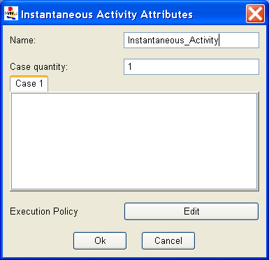
The SAN formalism models activities with two types of elements: timed activity and instantaneous activity. Right-clicking on an activity element pops up a menu that has an option to edit the activity. A dialog box similar to those shown in <xr id="fig:atomic_san_editor_time_activity" /> and <xr id="fig:atomic_san_editor_instantaneous_activity" /> may appear depending on the type of activity created.
<figure id="fig:atomic_san_editor_time_activity">
<figure id="fig:atomic_san_editor_instantaneous_activity">
The steps involved in defining the activities of the model element timed activity are as follows:
- Specify an activity distribution function by clicking the selector next to the desired distribution in the box titled Time distribution function. For analytic solutions, only exponential and deterministic distributions may be selected.
- Next, enter the parameters for the chosen distribution in the box below the combo-box. The headings on the box change depending on the distribution chosen. For the exponential distribution, only the rate, which is the reciprocal of the mean, is required. Section 1.2.5 of Modeling Background describes the distribution functions for timed activities in Möbius together with their parameters. The parameters can be expressions (double-precision values), global variables of type double, or series of statements. If statements are used, you must provide a return statement with a double-precision value equaling the parameter.
If more than one case is specified, an additional sub-window is present for specifying the case probabilities. Only one case is visible at a time, but you can step through the remaining cases by clicking on the tab of the case number.
Some points to be noted are:
- The first case probability corresponds to the top circle on the activity.
- Case probabilities can be expressions (double-precision values between zero and one), or series of statements (as in <xr id="fig:atomic_san_editor_time_activity" />). If a case probability is a series of statements, then you must provide a return statement with the desired value.
- Case probabilities may depend on the markings of places, but need not be connected to those places.
- Case probabilities can be functions of global variables, place markings, and extended place markings.
- Möbius automatically normalizes the case probabilities.
Execution policy
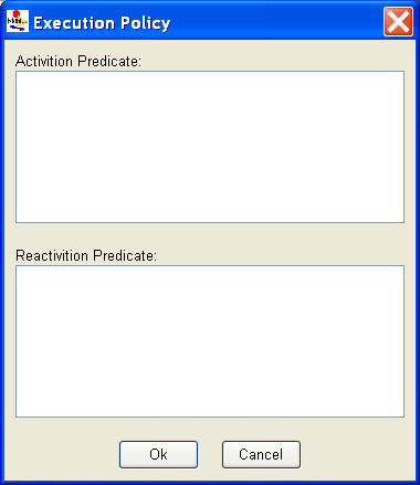
The execution policy editor is an advanced concept that only applies to simulation-based solutions and can be safely ignored for many models. Reactivation is disabled by default, and often this behavior is sufficient. Reactivation is disabled when both the activation and reactivation predicates are undefined, or have a defined value that is false. Refer to Section 1.2.4 of Modeling Background for more information on execution policy.
Reactivation is used to change the behavior of the activity during simulation. When reaction is disabled, the distribution function of an activity is sampled only during the state where the activity is first enabled (i.e., when all input gates associated with the activity are enabled. In more advanced scenarios, the behavior of the model might required that the activity might be activated again (re-activated) so that its distribution is resampled based on the new state of the model. In such cases, the user can set predicates in the Activation Predicate and Reactivation Predicate boxes. In each state where the activation predicate is true, the simulator will check the given activity to determine if it should be reactivated. If the reactivation predicate is also true in the current state, the activity will be reactivated, meaning a new delay will be sampled from the distribution function, and the activity will be scheduled to fire after “delay” units of time from the current simulation time. The reactivation predicate affects the activity only if the activity is already enabled (Modeling_Background#fig:action <xr id="fig:action" /> (d) of Modeling Background). Enabling of the activation predicate could possibly cause scenario (c) in Figure 3 of Modeling Background <xr id="fig:action" />.
<xr id="fig:atomic_san_editor_execution_policy" /> depicts the dialog box that appears with the Execution Policy editor.
<figure id="fig:atomic_san_editor_execution_policy">
Arcs and lines
In SAN models, three arc tools are used for drawing: straight, spline, and connected lines. You use them by selecting one of the arc tools with the left mouse button. Move the mouse to the desired point of origin of the line, and click the left button. Move the mouse to the desired locations of all intermediate points one by one, clicking the left mouse button (for splines and connected lines) to set down each point. When the destination is reached, click the left button. If one of the end points of the line cannot be identified as an appropriate object, an error message appears. You can avoid that by placing the end points clearly within the boundaries of the desired endpoint objects. Lines may overlap objects or other lines. You can cancel an arc you are drawing by right-clicking the mouse.
Note that lines are directed and thus may be drawn only between certain objects in a certain order as listed below:
- from a place to an activity
- from a place or an extended place to an input gate
- from an activity to a place
- from an activity to an output gate
- from an input gate to an activity
- from an output gate to a place or an extended place
Any other combination or order causes an error message to appear. An arrow is automatically placed at the head of the arc when you connect a place directly to an activity, or an activity directly to a place.
You do not need to draw arcs between input/output gates and the places/extended places. Doing so aids in keeping track of interaction between these elements. However, the arc can be left out if including it would clutter the model.
Text boxes
Text boxes have been provided to allow programmers to write comments about the model in the drawing area. They do not affect the behavior of the model in any way. Text boxes are meant to be useful tools for documenting parts of the model. To enter a text box within the drawing area, first select the Text Box element from the Element menu. Next, place the cursor (which appears as an arrow) by the object in the drawing area by which the text is to be entered and click on the left button. Write the text to be displayed in the pop-up dialog that appears. You can edit the text by right-clicking on the text box and selecting Edit.
Useful techniques
This section outlines tricks and techniques that advanced users might find helpful when constructing their models.
Simulation time
If you would like for components in the model to access the current simulation clock, its value can be accessed from C++ code within a given SAN component using this static class member:
BaseModelClass::LastActionTime. The definition of BaseModelClass can be found in <Mobius Installation Root>
/Cpp/BaseClasses/BaseModelClass.h.
The value is usable only when the model is solved via simulation; thus, models that depend on this value cannot be solved using the state-space-based numerical solution techniques available in Möbius.
Direct use of distribution functions
Advanced users have asked for the ability to generate random numbers using the same set of distribution functions that are used by Möbius. They can do so within the C++ code of SAN model components by adding code similar to this to the component definition:
static UserDistributions dist(0, 31415);
double delay=dist.Exponential(.5);
The first parameter passed to the UserDistributions constructor specifies the type of random number generator to use with this UserDistributions object (0 is Lagged Fibonacci; 1 is Tausworthe). The second parameter sets the initial seed of the random number generator (31415 is known to provide a relatively long period).
For a complete list of the available distribution functions and their arguments, please refer to this Möbius AFI header file:
<Mobius Installation Root>
/Cpp/simulator/Distributions.h.
References
- ↑ 1.0 1.1 J. F. Meyer, A. Movaghar, and W. H. Sanders. Stochastic activity networks: Structure, behavior, and application. In Proc. International Workshop on Timed Petri Nets, pages 106–115, Torino, Italy, July 1985.
- ↑ F. Bause and P. S. Kritzinger. Stochastic Petri Nets: An Introduction to the Theory. Vieweg, Braunschweig, 1996.
