Difference between revisions of "Building Models"

From Mobius Wiki
Jump to: navigation, search
Line 424: Line 424:
  
 
<figure id="fig:atomic_san_editor_user_type_definition">
 
<figure id="fig:atomic_san_editor_user_type_definition">
[[Image:atomic_san_editor.png|center|Figure 13: SAN user-type definition editor.]]
+
[[Image:atomic_san_editor_user_type_definition.png|center|Figure 13: SAN user-type definition editor.]]
 
<br/>
 
<br/>
 
<center>Figure 13: SAN user-type definition editor.</center></figure>
 
<center>Figure 13: SAN user-type definition editor.</center></figure>

Revision as of 19:49, 25 February 2014

Project Manager

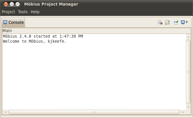
The Project Manager is the main console for Möbius and is shown in <xr id="fig:projman" />. Across the top is a main menu, with three menu categories: Project, Tools, and Help. The main display is a console view that shows messages for the operations performed by Möbius. Descriptions of the operations available under each menu category are presented in the following sections.


<figure id="fig:projman">

Figure 1: The Project Manager window.


Figure 1: The Project Manager window.
</figure>


Project Menu

The Project menu contains several operations related to Möbius projects. A Möbius project is the fundamental unit of organization for each system model in Möbius. A project contains one or more models defining the system and instances, descriptions of what parameters to solve for, and instances of solvers to generate the solutions. More details on projects can be found in Section 2.

The Project menu contains the following operations:

  • New: Create a new project. A dialog will appear prompting for the new project name. After you enter a valid project name, the author, and a description. The author and description are optional and for informational purposes only. These two fields can be changed at a later date. The new project will be opened.
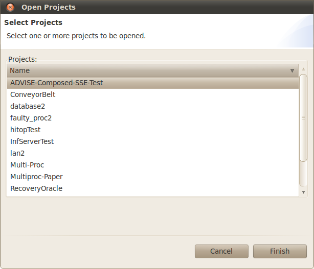
  • Open: Open an existing project. A dialog to select the project to open will appear as shown in <xr id="fig:project_dialog" />. You may select multiple projects to be opened simultaneously. You can quickly open a single project by double clicking it.


<figure id="fig:project_dialog">

Figure 2: Project selection dialog.


Figure 2: Use the project selection dialog to open projects.
</figure>


  • Copy: Copy an existing project to a new project. You must close the existing project to guarantee a stable copy.
  • Rename: Give an existing project a new name. You must close the project before it can be renamed.
  • Clean: Remove all temporary files from the project.
  • Resave: Regenerate all project source code and libraries. Resaving the project is required before a project is opened for the first time after a Möbius upgrade. You must also resave after unarchiving a project.
  • Delete: Delete the project. The most-recently-deleted project is stored in a “Deleted” folder within the Möbius project directory.
  • Archive: Create a backup of the project. After you select one or more projects, you will be asked for details about how you want each of the selected projects to be archived. After you specify the name of the archive file, you must select one of two options, Full archive and Minimal archive. A full archive includes all files found within the project. A minimal archive includes only the files necessary to define all models within the project. In a minimal archive, object files, libraries, executables, and results are not backed up. Minimal archives are helpful when multiple users are collaborating on the same model, since they create small archives that are convenient to email. The format for the archive is gzipped tar (.tgz) format.
  • Unarchive: Restore a project from an archive file. If the project to be restored has the same name as an existing project, you can either delete the existing project or cancel the restoration. Restoring one project on top of a different one could cause corruption and confusion, so is not supported. Unarchived projects should be resaved before they are used.
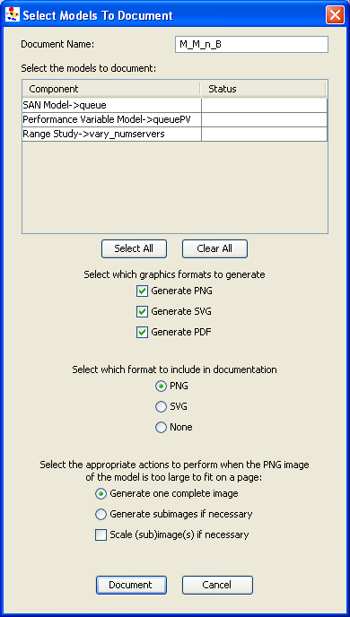
  • Document: Create HTML documentation for the chosen project. After you select the project to document, you use the Document Project dialog (see <xr id="fig:doc_proj" />) to select the models in the project that should be documented. Documentation is written to a subdirectory in the Documentation directory within the selected project’s project directory. The name of the subdirectory is given by the Document Name field in the dialog. You can view it with a web browser, or import it into software such as Microsoft Word for format refinement and printing.
Möbius supports three image formats for output: PNG, SVG, and PDF. You select which formats you want generated by selecting the appropriate checkboxes. Also, you can include one of these outputs into the generated HTML documentation.
There are four options in the dialog that are helpful when dealing with images that are too large to fit on a single page:
- Generate one complete image will create a single image for the model.
- Generate subimages if necessary will subdivide the full image in width and/or height and generate two or four subimages. The width is subdivided if the original image is more than 650 pixels wide. The height is subdivided if the original image is more than 700 pixels tall.
- Scale subimages will scale each subimage that is larger than a single page in size. The scaling is proportional and the resulting image will be at most 650 wide or 700 pixels tall.


<figure id="fig:doc_proj">

Figure 3: The Document Project dialog.


Figure 3: The Document Project dialog is used to select models from the project to include in the documentation.
</figure>


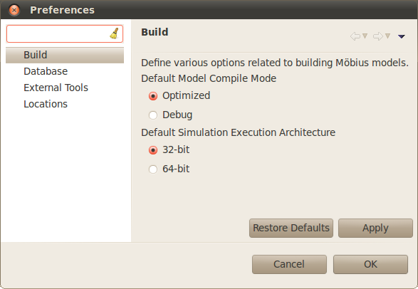
  • Preferences: Launch the preferences window (see <xr id="fig:projman_preferences" />).


<figure id="fig:projman_preferences">

Figure 4: The Möbius Preferences dialog.


Figure 4: The Möbius Preferences dialog is used to change various preferences about the operation of Möbius.
</figure>


  • Quit: Exit Möbius.

Preferences Dialog

The Preferences dialog (<xr id="fig:projman_preferences" />) provides access to various preferences and settings used during the operation of the Möbius tool. The preferences are broken down into pages listed on the left side of the dialog. Above the pages is a filter text box that you can quickly type a keyword in and the preference pages pertinent to that keyword will be displayed. For example, typing “user” in the filter box will eliminate all the pages except the Database page, because it contains a username field used by the database connection feature.

The Preferences dialog contains the following page:

  • Build: This preference page allows you to define the default compile mode and default simulation execution architecture. Möbius can compile in two modes: normal and optimized. Normal mode incorporates compiler-created debugging symbols into the object files, and uses debug-enabled Möbius AFI libraries when creating the executables, allowing project-generated executables (such as the simulator and state-space generator) to be run through C++ debuggers like gdb. Normal mode also enables Möbius trace output, making it possible to generate files that trace the progress of the model during solution. Normal mode object code takes less time to generate, but is often much larger than optimized code, due to the extra debugging symbols that are included.
Optimized mode enables full compiler optimizations, and disables debug symbols and trace output. Optimized mode should be used when the model is running well, and results need to be produced rapidly.
The results generated should be the same in either mode. The modes allow for the trade-off between extra information needed for debugging and speed of data production.
The default simulation execution architecture mode has two options: 32-bit and 64-bit. For machines running a 32-bit version of their operating system, this setting has no effect as simulations will always be executed in 32-bit mode. However, for machines running a 64-bit operating system, you have the option of building and executing 32-bit or 64-bit simulations. 32-bit simulations will likely run a little faster and take up significantly less memory during execution. However, 64-bit simulations enable access to greater amounts of memory space that may be necessary for large simulations. Simulation results in either mode should be the same.
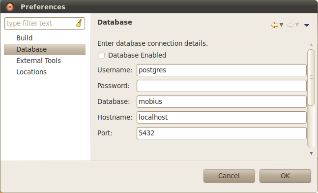
  • Database: The Database settings dialog displays the list settings that are needed to interface Möbius the integrated results database features with the external database server.


<figure id="fig:projman_db">

Figure 5: The Results Database preference page.


Figure 5: The Results Database preference page is used to specify the database access settings.
</figure>


- Database Enabled determines if Möbius will connect to the database server using the specified configuration settings.
- User Name specifies the name of the database user that Möbius should use when connecting to the database system.
- Password specifies the password for the indicated database user.
- Database is the name of the database Möbius will create. Multiple databases can be created as needed, simply by changing this name.
- Hostname is the name of the machine where the database server is located. Can be a full machine name or “localhost”.
- Port is the listening port of the database server. The default port is 5432. Ask your system administrator if the port was changed when the database server was configured.
  • External Tools: The External Tools preference page lists the external tools Möbius uses during its operation. In special cases, you may want to change the tool used to perform a certain operation (for example, the remote shell or archive command). The provided tool must either be in your PATH or the absolute path to the tool should be provided. Some fields are used to specify additional arguments to the external tool whenever it is called.
- Compiler: The G++ compiler that Möbius should use.
- Compiler Options: Extra compiler options to be used when compiling the Möbius project. This field was originally used to add debugging flags. In current versions, debugging flags are automatically added as part of the normal compilation mode, and this field should typically be blank.
- Linker: The linker, ld. Usually set to the path to the standard linker for the system.
- Linker Options: Extra linker options to be used when linking Möbius solvers (such as the simulator and state-space generator). For standard use, this field can be left blank.
- Make Command: The GNU make tool. The version of make should be 3.7x or later.
- Archive Command: The ar tool, the system command used to create C++ library files.
- Ranlib Command: The ranlib tool. Ranlib is used during the creation of project libraries.
- Remote Shell Command: The command used to gain remote access to other machines on the network. It is not necessary to specify a remote shell command to run Möbius on a single local machine. Typically this command is either rsh or ssh. In either case, system access privileges must be set so that the command can execute without entering a password or pass phrase. More details are available in Appendix section ?? and in the system man pages for rsh and ssh.
- Tar Command: The GNU tar command. This command is used to create and restore archive files. NOTE: In the current version of Möbius, tar is used with the “z” option, specifying the archive to be compressed with gzip. Typically gzip is installed in the same directory as tar, but most implementations of tar expect to find gzip in the PATH, and do not expect to have to look for it. If there are error messages when “archive” or “unarchive” commands are run, please see if gzip is found in the system PATH, and update the PATH if necessary.
  • Locations: The locations preference page contains a list of system paths necessary for the operation of Möbius.
- Möbius Installation Path: The directory where the Möbius software is installed. This field should update automatically, based on the location of the Möbius executable currently running. Möbius uses this directory to locate the Möbius AFI header files and libraries.
- Möbius Projects Directory: The directory containing the desired set of Möbius projects. It is possible to have multiple project directories, and changing this field switches from one to another. Most new users find one project directory is sufficient. The project path should not contain spaces. As a result, the default path on Windows is C:MobiusProject. If multiple people are using Möbius on the same machine, they should all give unique names for their Project directories.


Tools Menu

The Tools menu lists the various utilities available in Möbius. The Data Manager menu item will launch the Möbius Data Manager, which is further described in Section 1 of Utilities.


Help Menu

The Help menu provides various help for the use of Möbius. The About menu item opens the About window. The About window contains information about this version of Möbius, including the vendor and copyright statement.


Console View

The Console View provides a running output of the operations of Möbius. When a project is opened or a model component is saved, this event is logged by the console for your review. The Console View has several icons in the upper right corner to control the behavior of the console and to switch between the available console logs.

The first icon looks like a document with a grey X over it. This icon clears all the text from the current console log. This can be useful for when you want a fresh start to the log.

The next icon has a lock over a scrolling control. This is the scroll lock and will prevent the console from autumatically scrolling down as new text is appended to the console.

The next icon has pin on a window icon. This is the pin console button and will keep the console view from switching to a different console automatically.

Finally, the last icon allows you to switch between the available console logs. The Main console provides general information about the operation of Möbius. The Error console provides detailed error messages when something goes wrong. The Detailed console provides the finest grain of detail messages possible and includes messages from the other two consoles. Of particular interest, when Möbius executes an external command (e.g. make, java, etc.) the command and its arguments are logged in the Detailed console.

The text of a console log can be highlighted for copy/paste operations like you would expect. Also, if you right click on the text, a simple find feature is available to quickly search through the contents of the log.


Project Editor

The Möbius project is the fundamental unit of organization for each system model in Möbius. A complete project will contain the following: one or more models defining the system behavior, a description of what to measure about the system, specification of all model parameters, at least one instantiation of a solver to compute the required measurements, and the results produced by the solver.


Tree View

The model types in the project are classified in the same hierarchy as the components of the Möbius framework (see section 1 of Modeling Background). The model types that may exist in a project are listed below.

  • Atomic models describe the behavior of individual components of the system.
  • Composed models are hierarchical models used to combine atomic and composed models to form the complete model of the system.
  • Reward models define measures of interest about the system.
  • Study models create experiments that specify values for the system parameters in the model.
  • Solvers solve the model using simulation, or prepare the model for numerical solution using state-space generation.
  • Numerical solvers solve the model using a variety of numerical algorithms.

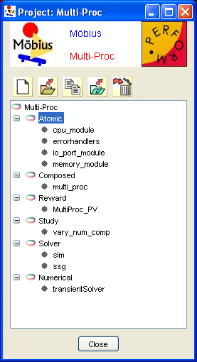
The model types are arranged in a tree, in which the names of the various classifications are the main nodes, and the instances of each classification are the children of the node. The tree view from an example project editor is shown in <xr id="fig:project_main" />.


<figure id="fig:project_main">

Figure 6: Tree view.


Figure 6: Tree view in the project editor, with Atomic selected.
</figure>


The order of model types in the tree represents the typical dependency among models in a project. A model of a given type typically depends on models of the type one level above it in the tree. For example, a study model depends on a reward model. When one model depends on another, it is often referred to as the parent, and the model it depends on is referred to as the child.


Project Operations

Several operations are possible in the project editor. You can access the operations via the toolbar or through a pop-up menu activated by right-clicking within the tree view.


New     To create a new model within a project, select the desired category and click on New. A dialog will appear, asking for the type of formalism to create. For example, <xr id="fig:project_child" />(a) displays the possible types of atomic models that can be created. The dialog also gives the opportunity to name the new model.

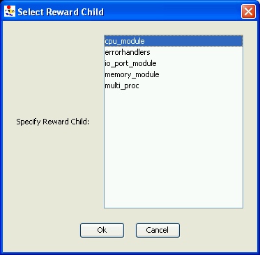
After you click the OK button, the new model editor will open. In the case of the reward, study, solver, and numerical solver models, another pop-up dialog will immediately appear, requesting the name of the child model of the new model, as shown in <xr id="fig:project_child" />(b).
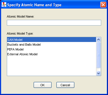

Figure 7(a): Types of atomic models. <figure id="fig:project_child">Figure 7(b): Name for newly created child model's model.</figure>
(a) Specify the name and type of newly created models. (b) Specify the newly created model’s child model.
Figure 7: Dialogs shown when a new Möbius model is created.


Open     Select a model name from the tree view, and then click Open to open it. Multiple models may be open at the same time.


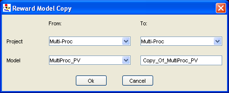
Copy     Select a model name or type from the tree view, and then click Copy to generate a copy of the model. Another dialog opens, allowing you to copy the selected model to another file within this project, or copy it into another project. Also, you can copy models from another project into the current one.


<figure id="fig:project_copy">

Figure 8: The copy dialog.


Figure 8: An instance of the copy dialog, which is used to copy models within a project, or from one project to another.
</figure>


Import     Select a model type in the tree view and then click Import to import this type of model from an existing UltraSAN1 project. A dialog will appear, listing all the UltraSAN projects found in the UltraSAN project directory (see Section ?? on how to set the UltraSAN project directory). After you select one of the UltraSAN projects, another dialog will appear listing all possible models in the UltraSAN project of the type selected in Möbius.

1 UltraSAN was the predecessor to Möbius.


Delete     You can delete a model in a Möbius project by selecting the model in the tree view and choosing the Delete menu.


Close     You can close the project editor using the Close button, after all of the model editors of the project have been closed.

Project Directory Structure

Each project is stored in a directory named after the project within the Möbius project directory. It is necessary to understand the basic structure of a project directory, since Möbius stores output files, such as solution results or model documentation, in various locations within the project subtree. Files within the project directory are arranged in the same tree structure as the tree view.

Solution results and other solver outputs are typically written to the model directory corresponding to the solver that generated the results.

All documentation is stored in a subdirectory of the Documentation directory in the top-level directory of the project. The name of this subdirectory is given by the Document Name field in the Document Project dialog. See <xr id="fig:doc_proj" /> for an example.

The project and each model in the project are defined in separate files, which are also named after the project or individual model and have extensions unique to each type of model. The files are XML-based, and under most circumstances should not be edited directly. Doing so can corrupt the Möbius project.


Constraints Checker

When a project, or a submodel within the project, is saved in the Project Editor, the constraints checker is called by the Project Manager to ensure that the model, as saved, doesn’t violate any conditions imposed upon it by solver modules which utilize the model. If the constraints checker detects a violation of a constraint, it produces a pop-up warning informing the user of the problem, prompting them to correct the issue.

For more on specific constraints for individual solvers, see section 4 of Solving Models.


Model Editors

Common Menus

There are several menus that are common to each model editor in Möbius. Instead of describing these features repeatedly, the functionality common to each model editor is discussed in this section.

File

The File menu is common to all editors, and typically contains the following common commands:

  • Save: Store the current model to disk, and then translate the model into the appropriate C++ code and compile the code to form the representative library for this model.
  • Save No Compile: Store the current model to disk, but avoid performing the compilation. It is still necessary to compile the model, either by selecting Save from the File menu, or by compiling within the solver.
  • Close: Close the editor. If there are unsaved changes, a dialog will appear, prompting you to save before closing.
  • Document Model: Create HTML documentation for the current model. The documentation files will be stored in a subdirectory in the Documentation directory within the project’s project directory. The name of the subdirectory will be what you specify in the Document Name field of the dialog box. See <xr id="fig:doc_proj" />.

Edit

Undo

You are allowed to undo most recent operations on the model using the Undo menu. Examples of operations that can be revoked using the undo feature include the movement of graphical components in an editor, the renaming of components, the editing of text, the addition of new components, and the addition of lines. The Undo menu will list the name of the most recently completed operation that can be undone. Undo operations are stored so that multiple operations can be undone.


Edit global variables

The behavior of complex systems being modeled often depends on several parameters. Often these parameters are unknown, or can take on multiple values, depending on the configuration of the system. Möbius provides the option of using global variables instead of pure numerical values to define the different characteristics of elements like state variables and actions. The values of the global variables are then set by experiments in the study model.

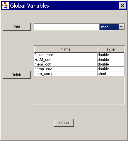
In each atomic or composed model, you can add or delete global variables by clicking on the Edit Global Variables option on the menu editor. A pop-up dialog box, as shown in <xr id="fig:atomic_san_editor_global_variables" />, is used to add, delete, and view global variables. The dialog box can remain open as a reference while you are editing the model.


<figure id="fig:atomic_san_editor_global_variables">

Figure 9: Global Variables editor.


Figure 9: Global Variables editor.
</figure>


  • The Add button is used to create new global variables. The combo-box on the top-right corner lists the available data types for the global variable. Only the standard data types that C++ directly supports are currently allowed (char, double, int, long, float, and short).
  • The Delete button is used to delete the selected global variables.
  • The Close button is used to hide the Global Variables editor dialog box.


User-defined functions

While building models, you might find it useful to define functions for the model using C++ header files and libraries. These functions are stored in C++ header (.h) or possibly source (.cpp) files that you must create. The files can be placed anywhere, but most often are stored in a new subdirectory in the project. If you are using C++ source files (.cpp), you will also need to place into the same directory a Makefile that will compile the source files into a library. The simplest way to create the Makefile is to copy one from an atomic model in your project and modify it to compile the library. With the current version of Möbius, you must compile the library manually before running a solver. Otherwise, an error message stating the library is missing will appear when the compiler tries to link with the user-defined library in the solver.

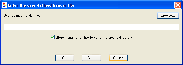
After you have successfully compiled the source code and created the library, you need to let Möbius know the location of the functions. You can do this by opening any model and selecting User-Defined Header under the Edit menu. A dialog box will pop up, asking for the location of your header (see <xr id="fig:atomic_san_editor_user_defined_header" />).


<figure id="fig:atomic_san_editor_user_defined_header">

Figure 10: User-defined header editor.


Figure 10: User-defined header editor.
</figure>


Enter the path to the C++ header file. There is a check box that instructs Möbius to store the header file path relative to your Möbius project directory. You should check it if your header files are stored in a subdirectory of your project, as it makes it easier to share your project with other users, or relocate it to different systems. If the path entered is incorrect, or the file has not yet been created, Möbius will display an error message.


<figure id="fig:atomic_san_editor_user_defined_library">

Figure 11: User-defined library editor.


Figure 11: User-defined library editor.
</figure>


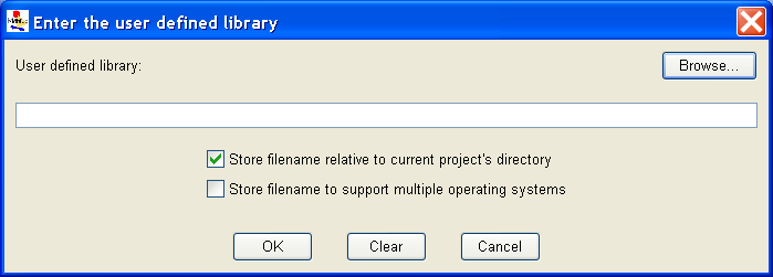
If you are also using a user-defined library, repeat the same operation for the library (see <xr id="fig:atomic_san_editor_user_defined_library" />). This dialog contains the same relative path checkbox found in the User-Defined Header dialog. It also contains another checkbox that makes it possible to support multiple operating system versions of the user-defined library. This feature will only work if the library name contains the name of the current operating system: Solaris, Linux, or Windows. After you check this box, the operating system name is replaced with $ARCH. When Möbius compiles your project on each operating system, $ARCH is replaced with the name of the appropriate operating system.

User-defined functions can be extremely useful if you are trying to make models more modular, or if multiple elements, such as SAN output gates, within the model are performing similar operations. In fact, you can even define functions that would modify the values of elements within the model (for example, a place within a SAN). Here are a few examples in which user-defined functions are helpful:

  • If your model contains complex functions that are repeatedly used or susceptible to change, you can write them in the library and simply call them from the model. For example, to define a comparison between two extended places that are arrays of 2 integers, you can create the following function in the library:
inline int is_lower(int x1, int y1,
int x2, int y2) {
if (x1<x2) return 1;
else if (x1 == x2) {
if (y1 <= y2) return 1;
else return 0;
}
else return 0;
}
The following code shows how to use the function in the model:
short result = is_lower(Place1->x, Place1->y,
Place2->x, Place2->y);
if (result == 1)
...
  • In the same way, you can define enabling conditions for activities using user-defined functions:
inline int activity_enable(int value1,
int value2) {
int ret=0;
if (value1==0 && value2==0)
ret=1;
...
return ret;
}
The enabling function of the corresponding input gate would then call the user-defined function, as follows:
activity_enable(Command1->Mark(),
Command2->Mark(), Group_ID->Mark(),
Component_ID->Mark(),
Component_type->Mark())
  • If you have an extended place in your model with a type that is a large array, matrix, or structure, it is possible to write a user-defined function to initialize the extended place. If you want to create unique experiments that define different initial values for this extended place, you can create a single global variable, and then write the user-defined function so that the extended place is initialized with different values, based on the value of the global variable. Then in the study you only need to adjust one value to change the definition of all fields in the extended place.


Atomic Formalisms

Each model is composed of one or more submodels, also referred to as atomic models. You can create and edit atomic models using different editors like the SAN editor, the PEPA editor, the Buckets and Balls editor, and the Fault Tree editor.


SAN

Möbius supports multiple formalisms, including stochastic activity networks (SANs). SANs[1] are stochastic extensions to Petri nets[2]. Using graphical primitives, SANs provide a high-level modeling formalism with which detailed performance, dependability, and performability models can be specified relatively easily.

SAN primitives

SANs consist of four primitive objects: places, activities, input gates, and output gates. Activities represent actions of the modeled system. Places represent the state of the modeled system. Input gates are used to control the “enabling” of activities, and output gates are used to change the state of the system when an activity “completes.”


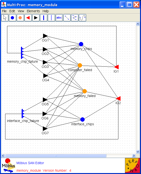
Places     Places represent the state of the modeled system. They are represented graphically as circles. In <xr id="fig:atomic_san_editor" />, memory_chips, interface_chips, memory_failed, and computer_failed are places. Each place contains a certain number of tokens, which represents the marking of the place. The set of all place markings represents the marking of the stochastic activity network. Note that tokens in a place are homogeneous, in that only the number of tokens in a place is known; there is no identification of different kinds of tokens within a place.


<figure id="fig:atomic_san_editor">

Figure 12: Möbius SAN Editor.


Figure 12: Möbius SAN Editor.
</figure>


The meaning of the marking of a place is arbitrary. For example, the number of tokens in a place could represent a number of objects, such as a number of tasks awaiting service. Also, the number of tokens in a place could represent an object of a certain type, such as a task with a certain priority level. This dual nature of a place marking provides a great deal of flexibility in modeling the dynamics of a system.


Activities     Activities represent actions in the modeled system that take some specified amount of time to complete. They are of two types: timed and instantaneous. Timed activities have durations that impact the performance of the modeled system, such as a packet transmission time or the time associated with a retransmission timer. Timed activities are represented graphically as thick vertical lines. In <xr id="fig:atomic_san_editor" />, memory_chip_failure and interface_chip_failure are timed activities. Each timed activity has an activity time distribution function associated with its duration. Activity time distribution functions can be generally distributed random variables. Each distribution can depend on the marking of the network. For example, one distribution parameter could be a constant multiplied by the marking of a certain place. Instantaneous activities represent actions that complete immediately when enabled in the system. They are represented graphically as thin vertical lines. No instantaneous activities are represented in <xr id="fig:atomic_san_editor" />. Case probabilities, represented graphically as circles on the right side of an activity, model uncertainty associated with the completion of an activity. Each case stands for a possible outcome, such as a routing choice in a network, or a failure mode in a faulty system. In <xr id="fig:atomic_san_editor" />, activity interface_chip_failure has three cases. Each activity has a probability distribution, called the case distribution, associated with its cases. This distribution can depend on the marking of the network at the moment of completion of an activity. If no circles are shown on an activity, one case is assumed with a probability of one.

An activity is enabled when the predictes of all input gates connected to the activity are true, and all places connected to incoming arcs contain tokens, i.e. have non zero markings. Once enabled, the activity samples its delay distribution function to determine the time delay before the activity fires. When the activity fires it updates the state of the model by subtracting tokens from places connected by incoming arcs, adding tokens to places connected by outgoing arcs, and executing the functions in input and output gates. The specific order that the state updates occur is: input gates, input arcs, output gates, and finally output arcs.

Please be aware that the order in which state updates occur in Möbius differs from UltraSAN. Gates are executed before arcs in Möbius, but the opposite was true in UltraSAN. Also, if there are multiple instances of the same item, for instance multiple input gates, the order of application of the gates is not specified. Models must be constructed so that the gate functions are execution order independent any time there are multiple instances of the same type of gates connected to an activity.

Also associated with each activity is a reactivation function. This function gives marking dependent conditions under which an activity is reactivated. Reactivation of an activated activity means that the activity is aborted and that a new activity time is immediately obtained from the activity time distribution. The reactivation function consists of an activation predicate and a reactivation predicate. An activity will be reactivated at the moment of a marking change if (1) the reactivation predicate holds for the new marking, (2) the activity remains enabled, and (3) the activation predicate holds for the marking in which the activity was originally activated.


Input gates     Input gates control the enabling of activities and define the marking changes that will occur when an activity completes. They are represented graphically as triangles. In <xr id="fig:atomic_san_editor" />, IG1 and IG2 are input gates. On the other side of the triangle is a set of arcs to the places upon which the gate depends, also called input places. Each input gate is defined with an enabling predicate and a function. The enabling predicate is a Boolean function that controls whether the connected activity is enabled. It can be any function of the markings of the input places. The input gate function defines the marking changes that occur when the activity completes.

If a place is directly connected to an activity with an arc, it is equivalent to an input gate with a predicate that enables the activity whenever the place has more than zero tokens along with a function that decrements the marking of the place whenever the activity fires.


Output gates     Like input gates, output gates define the marking changes that will occur when activities complete. The only difference is that an output gate is associated with a single case. An output gate is represented graphically as a triangle with its flat side connected to an activity or a case. In <xr id="fig:atomic_san_editor" />, OG1, OG2,..., OG6, and OG7 are output gates. On the other side of the triangle is a set of arcs to the places affected by the marking changes. An output gate is defined only with a function. The function defines the marking changes that occur when the activity completes. There is also a default scenario for output gates. If an activity is directly connected to a place, it is equivalent to an activation in which an output gate has a function that increments the marking of the place whenever the activity is fired.

More information on SANs can be found in [1]. The next few sections describe the various features available in the SAN editor to develop a SAN model.

Editor

This section looks into the atomic formalism that represents stochastic activity networks with emphasis on creation, editing, and manipulation of atomic models using the Möbius SAN editor. Refer to Section 2 for details on how to create and open a SAN model.

The names of the selected project and subnet appear in the top left corner (see <xr id="fig:atomic_san_editor" />). The large gridded area in the center is the drawing area . In the case of a new model, this gridded area is blank. Like most applications, the editor lists the menu horizontally at the top of the application’s current active window. If you click on a menu item, it drops a tool panel containing several options. The menu items and tool panel options are used to create and draw in the SAN formalism, as discussed below.

As discussed in Section 3.1, many menus are common to all model editors within Möbius. Please see Section 3.1 for detailed descriptions of the common editor functions. The following paragraphs will discuss the functionality that is unique to the SAN editor.

Edit

Type definitions

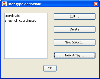
The SAN formalism supports a special element called extended place that allows the model to handle the representation of structures and arrays of primitive data-types. Clicking on Type Editor opens the dialog box shown in <xr id="fig:atomic_san_editor_user_type_definition" />. In this dialog box, you can create new structures and arrays that can be associated with extended places.


<figure id="fig:atomic_san_editor_user_type_definition">

Figure 13: SAN user-type definition editor.


Figure 13: SAN user-type definition editor.
</figure>


Möbius

Möbius

Motivation

Solution

Graph

Database Möbius Documentation

“”

<equation id="eqn:binom" shownumber>

f(k)=\binom{n}{k}p^k(1-p)^{n-k}\quad k=0,1,\dots,n

</equation>

Sort of like <xr id="eqn:binom" />, but not really.


References

  1. 1.0 1.1 J. F. Meyer, A. Movaghar, and W. H. Sanders. Stochastic activity networks: Structure, behavior, and application. In Proc. International Workshop on Timed Petri Nets, pages 106–115, Torino, Italy, July 1985.
  2. F. Bause and P. S. Kritzinger. Stochastic Petri Nets: An Introduction to the Theory. Vieweg, Braunschweig, 1996.
Project Manager[edit]

The Project Manager is the main console for Möbius and is shown in <xr id="fig:projman" />. Across the top is a main menu, with three menu categories: Project, Tools, and Help. The main display is a console view that shows messages for the operations performed by Möbius. Descriptions of the operations available under each menu category are presented in the following sections.


<figure id="fig:projman">

Figure 1: The Project Manager window.


Figure 1: The Project Manager window.
</figure>


Project Menu[edit]

The Project menu contains several operations related to Möbius projects. A Möbius project is the fundamental unit of organization for each system model in Möbius. A project contains one or more models defining the system and instances, descriptions of what parameters to solve for, and instances of solvers to generate the solutions. More details on projects can be found in Section 2.

The Project menu contains the following operations:

  • New: Create a new project. A dialog will appear prompting for the new project name. After you enter a valid project name, the author, and a description. The author and description are optional and for informational purposes only. These two fields can be changed at a later date. The new project will be opened.
  • Open: Open an existing project. A dialog to select the project to open will appear as shown in <xr id="fig:project_dialog" />. You may select multiple projects to be opened simultaneously. You can quickly open a single project by double clicking it.


<figure id="fig:project_dialog">

Figure 2: Project selection dialog.


Figure 2: Use the project selection dialog to open projects.
</figure>


  • Copy: Copy an existing project to a new project. You must close the existing project to guarantee a stable copy.
  • Rename: Give an existing project a new name. You must close the project before it can be renamed.
  • Clean: Remove all temporary files from the project.
  • Resave: Regenerate all project source code and libraries. Resaving the project is required before a project is opened for the first time after a Möbius upgrade. You must also resave after unarchiving a project.
  • Delete: Delete the project. The most-recently-deleted project is stored in a “Deleted” folder within the Möbius project directory.
  • Archive: Create a backup of the project. After you select one or more projects, you will be asked for details about how you want each of the selected projects to be archived. After you specify the name of the archive file, you must select one of two options, Full archive and Minimal archive. A full archive includes all files found within the project. A minimal archive includes only the files necessary to define all models within the project. In a minimal archive, object files, libraries, executables, and results are not backed up. Minimal archives are helpful when multiple users are collaborating on the same model, since they create small archives that are convenient to email. The format for the archive is gzipped tar (.tgz) format.
  • Unarchive: Restore a project from an archive file. If the project to be restored has the same name as an existing project, you can either delete the existing project or cancel the restoration. Restoring one project on top of a different one could cause corruption and confusion, so is not supported. Unarchived projects should be resaved before they are used.
  • Document: Create HTML documentation for the chosen project. After you select the project to document, you use the Document Project dialog (see <xr id="fig:doc_proj" />) to select the models in the project that should be documented. Documentation is written to a subdirectory in the Documentation directory within the selected project’s project directory. The name of the subdirectory is given by the Document Name field in the dialog. You can view it with a web browser, or import it into software such as Microsoft Word for format refinement and printing.
Möbius supports three image formats for output: PNG, SVG, and PDF. You select which formats you want generated by selecting the appropriate checkboxes. Also, you can include one of these outputs into the generated HTML documentation.
There are four options in the dialog that are helpful when dealing with images that are too large to fit on a single page:
- Generate one complete image will create a single image for the model.
- Generate subimages if necessary will subdivide the full image in width and/or height and generate two or four subimages. The width is subdivided if the original image is more than 650 pixels wide. The height is subdivided if the original image is more than 700 pixels tall.
- Scale subimages will scale each subimage that is larger than a single page in size. The scaling is proportional and the resulting image will be at most 650 wide or 700 pixels tall.


<figure id="fig:doc_proj">

Figure 3: The Document Project dialog.


Figure 3: The Document Project dialog is used to select models from the project to include in the documentation.
</figure>


  • Preferences: Launch the preferences window (see <xr id="fig:projman_preferences" />).


<figure id="fig:projman_preferences">

Figure 4: The Möbius Preferences dialog.


Figure 4: The Möbius Preferences dialog is used to change various preferences about the operation of Möbius.
</figure>


  • Quit: Exit Möbius.

Preferences Dialog[edit]

The Preferences dialog (<xr id="fig:projman_preferences" />) provides access to various preferences and settings used during the operation of the Möbius tool. The preferences are broken down into pages listed on the left side of the dialog. Above the pages is a filter text box that you can quickly type a keyword in and the preference pages pertinent to that keyword will be displayed. For example, typing “user” in the filter box will eliminate all the pages except the Database page, because it contains a username field used by the database connection feature.

The Preferences dialog contains the following page:

  • Build: This preference page allows you to define the default compile mode and default simulation execution architecture. Möbius can compile in two modes: normal and optimized. Normal mode incorporates compiler-created debugging symbols into the object files, and uses debug-enabled Möbius AFI libraries when creating the executables, allowing project-generated executables (such as the simulator and state-space generator) to be run through C++ debuggers like gdb. Normal mode also enables Möbius trace output, making it possible to generate files that trace the progress of the model during solution. Normal mode object code takes less time to generate, but is often much larger than optimized code, due to the extra debugging symbols that are included.
Optimized mode enables full compiler optimizations, and disables debug symbols and trace output. Optimized mode should be used when the model is running well, and results need to be produced rapidly.
The results generated should be the same in either mode. The modes allow for the trade-off between extra information needed for debugging and speed of data production.
The default simulation execution architecture mode has two options: 32-bit and 64-bit. For machines running a 32-bit version of their operating system, this setting has no effect as simulations will always be executed in 32-bit mode. However, for machines running a 64-bit operating system, you have the option of building and executing 32-bit or 64-bit simulations. 32-bit simulations will likely run a little faster and take up significantly less memory during execution. However, 64-bit simulations enable access to greater amounts of memory space that may be necessary for large simulations. Simulation results in either mode should be the same.
  • Database: The Database settings dialog displays the list settings that are needed to interface Möbius the integrated results database features with the external database server.


<figure id="fig:projman_db">

Figure 5: The Results Database preference page.


Figure 5: The Results Database preference page is used to specify the database access settings.
</figure>


- Database Enabled determines if Möbius will connect to the database server using the specified configuration settings.
- User Name specifies the name of the database user that Möbius should use when connecting to the database system.
- Password specifies the password for the indicated database user.
- Database is the name of the database Möbius will create. Multiple databases can be created as needed, simply by changing this name.
- Hostname is the name of the machine where the database server is located. Can be a full machine name or “localhost”.
- Port is the listening port of the database server. The default port is 5432. Ask your system administrator if the port was changed when the database server was configured.
  • External Tools: The External Tools preference page lists the external tools Möbius uses during its operation. In special cases, you may want to change the tool used to perform a certain operation (for example, the remote shell or archive command). The provided tool must either be in your PATH or the absolute path to the tool should be provided. Some fields are used to specify additional arguments to the external tool whenever it is called.
- Compiler: The G++ compiler that Möbius should use.
- Compiler Options: Extra compiler options to be used when compiling the Möbius project. This field was originally used to add debugging flags. In current versions, debugging flags are automatically added as part of the normal compilation mode, and this field should typically be blank.
- Linker: The linker, ld. Usually set to the path to the standard linker for the system.
- Linker Options: Extra linker options to be used when linking Möbius solvers (such as the simulator and state-space generator). For standard use, this field can be left blank.
- Make Command: The GNU make tool. The version of make should be 3.7x or later.
- Archive Command: The ar tool, the system command used to create C++ library files.
- Ranlib Command: The ranlib tool. Ranlib is used during the creation of project libraries.
- Remote Shell Command: The command used to gain remote access to other machines on the network. It is not necessary to specify a remote shell command to run Möbius on a single local machine. Typically this command is either rsh or ssh. In either case, system access privileges must be set so that the command can execute without entering a password or pass phrase. More details are available in Appendix section ?? and in the system man pages for rsh and ssh.
- Tar Command: The GNU tar command. This command is used to create and restore archive files. NOTE: In the current version of Möbius, tar is used with the “z” option, specifying the archive to be compressed with gzip. Typically gzip is installed in the same directory as tar, but most implementations of tar expect to find gzip in the PATH, and do not expect to have to look for it. If there are error messages when “archive” or “unarchive” commands are run, please see if gzip is found in the system PATH, and update the PATH if necessary.
  • Locations: The locations preference page contains a list of system paths necessary for the operation of Möbius.
- Möbius Installation Path: The directory where the Möbius software is installed. This field should update automatically, based on the location of the Möbius executable currently running. Möbius uses this directory to locate the Möbius AFI header files and libraries.
- Möbius Projects Directory: The directory containing the desired set of Möbius projects. It is possible to have multiple project directories, and changing this field switches from one to another. Most new users find one project directory is sufficient. The project path should not contain spaces. As a result, the default path on Windows is C:MobiusProject. If multiple people are using Möbius on the same machine, they should all give unique names for their Project directories.


Tools Menu[edit]

The Tools menu lists the various utilities available in Möbius. The Data Manager menu item will launch the Möbius Data Manager, which is further described in Section 1 of Utilities.


Help Menu[edit]

The Help menu provides various help for the use of Möbius. The About menu item opens the About window. The About window contains information about this version of Möbius, including the vendor and copyright statement.


Console View[edit]

The Console View provides a running output of the operations of Möbius. When a project is opened or a model component is saved, this event is logged by the console for your review. The Console View has several icons in the upper right corner to control the behavior of the console and to switch between the available console logs.

The first icon looks like a document with a grey X over it. This icon clears all the text from the current console log. This can be useful for when you want a fresh start to the log.

The next icon has a lock over a scrolling control. This is the scroll lock and will prevent the console from autumatically scrolling down as new text is appended to the console.

The next icon has pin on a window icon. This is the pin console button and will keep the console view from switching to a different console automatically.

Finally, the last icon allows you to switch between the available console logs. The Main console provides general information about the operation of Möbius. The Error console provides detailed error messages when something goes wrong. The Detailed console provides the finest grain of detail messages possible and includes messages from the other two consoles. Of particular interest, when Möbius executes an external command (e.g. make, java, etc.) the command and its arguments are logged in the Detailed console.

The text of a console log can be highlighted for copy/paste operations like you would expect. Also, if you right click on the text, a simple find feature is available to quickly search through the contents of the log.


Project Editor[edit]

The Möbius project is the fundamental unit of organization for each system model in Möbius. A complete project will contain the following: one or more models defining the system behavior, a description of what to measure about the system, specification of all model parameters, at least one instantiation of a solver to compute the required measurements, and the results produced by the solver.


Tree View[edit]

The model types in the project are classified in the same hierarchy as the components of the Möbius framework (see section 1 of Modeling Background). The model types that may exist in a project are listed below.

  • Atomic models describe the behavior of individual components of the system.
  • Composed models are hierarchical models used to combine atomic and composed models to form the complete model of the system.
  • Reward models define measures of interest about the system.
  • Study models create experiments that specify values for the system parameters in the model.
  • Solvers solve the model using simulation, or prepare the model for numerical solution using state-space generation.
  • Numerical solvers solve the model using a variety of numerical algorithms.

The model types are arranged in a tree, in which the names of the various classifications are the main nodes, and the instances of each classification are the children of the node. The tree view from an example project editor is shown in <xr id="fig:project_main" />.


<figure id="fig:project_main">

Figure 6: Tree view.


Figure 6: Tree view in the project editor, with Atomic selected.
</figure>


The order of model types in the tree represents the typical dependency among models in a project. A model of a given type typically depends on models of the type one level above it in the tree. For example, a study model depends on a reward model. When one model depends on another, it is often referred to as the parent, and the model it depends on is referred to as the child.


Project Operations[edit]

Several operations are possible in the project editor. You can access the operations via the toolbar or through a pop-up menu activated by right-clicking within the tree view.


New     To create a new model within a project, select the desired category and click on New. A dialog will appear, asking for the type of formalism to create. For example, <xr id="fig:project_child" />(a) displays the possible types of atomic models that can be created. The dialog also gives the opportunity to name the new model.

After you click the OK button, the new model editor will open. In the case of the reward, study, solver, and numerical solver models, another pop-up dialog will immediately appear, requesting the name of the child model of the new model, as shown in <xr id="fig:project_child" />(b).


Figure 7(a): Types of atomic models. <figure id="fig:project_child">Figure 7(b): Name for newly created child model's model.</figure>
(a) Specify the name and type of newly created models. (b) Specify the newly created model’s child model.
Figure 7: Dialogs shown when a new Möbius model is created.


Open     Select a model name from the tree view, and then click Open to open it. Multiple models may be open at the same time.


Copy     Select a model name or type from the tree view, and then click Copy to generate a copy of the model. Another dialog opens, allowing you to copy the selected model to another file within this project, or copy it into another project. Also, you can copy models from another project into the current one.


<figure id="fig:project_copy">

Figure 8: The copy dialog.


Figure 8: An instance of the copy dialog, which is used to copy models within a project, or from one project to another.
</figure>


Import     Select a model type in the tree view and then click Import to import this type of model from an existing UltraSAN1 project. A dialog will appear, listing all the UltraSAN projects found in the UltraSAN project directory (see Section ?? on how to set the UltraSAN project directory). After you select one of the UltraSAN projects, another dialog will appear listing all possible models in the UltraSAN project of the type selected in Möbius.

1 UltraSAN was the predecessor to Möbius.


Delete     You can delete a model in a Möbius project by selecting the model in the tree view and choosing the Delete menu.


Close     You can close the project editor using the Close button, after all of the model editors of the project have been closed.

Project Directory Structure[edit]

Each project is stored in a directory named after the project within the Möbius project directory. It is necessary to understand the basic structure of a project directory, since Möbius stores output files, such as solution results or model documentation, in various locations within the project subtree. Files within the project directory are arranged in the same tree structure as the tree view.

Solution results and other solver outputs are typically written to the model directory corresponding to the solver that generated the results.

All documentation is stored in a subdirectory of the Documentation directory in the top-level directory of the project. The name of this subdirectory is given by the Document Name field in the Document Project dialog. See <xr id="fig:doc_proj" /> for an example.

The project and each model in the project are defined in separate files, which are also named after the project or individual model and have extensions unique to each type of model. The files are XML-based, and under most circumstances should not be edited directly. Doing so can corrupt the Möbius project.


Constraints Checker[edit]

When a project, or a submodel within the project, is saved in the Project Editor, the constraints checker is called by the Project Manager to ensure that the model, as saved, doesn’t violate any conditions imposed upon it by solver modules which utilize the model. If the constraints checker detects a violation of a constraint, it produces a pop-up warning informing the user of the problem, prompting them to correct the issue.

For more on specific constraints for individual solvers, see section 4 of Solving Models.


Model Editors[edit]

Common Menus[edit]

There are several menus that are common to each model editor in Möbius. Instead of describing these features repeatedly, the functionality common to each model editor is discussed in this section.

File[edit]

The File menu is common to all editors, and typically contains the following common commands:

  • Save: Store the current model to disk, and then translate the model into the appropriate C++ code and compile the code to form the representative library for this model.
  • Save No Compile: Store the current model to disk, but avoid performing the compilation. It is still necessary to compile the model, either by selecting Save from the File menu, or by compiling within the solver.
  • Close: Close the editor. If there are unsaved changes, a dialog will appear, prompting you to save before closing.
  • Document Model: Create HTML documentation for the current model. The documentation files will be stored in a subdirectory in the Documentation directory within the project’s project directory. The name of the subdirectory will be what you specify in the Document Name field of the dialog box. See <xr id="fig:doc_proj" />.

Edit[edit]

Undo

You are allowed to undo most recent operations on the model using the Undo menu. Examples of operations that can be revoked using the undo feature include the movement of graphical components in an editor, the renaming of components, the editing of text, the addition of new components, and the addition of lines. The Undo menu will list the name of the most recently completed operation that can be undone. Undo operations are stored so that multiple operations can be undone.


Edit global variables

The behavior of complex systems being modeled often depends on several parameters. Often these parameters are unknown, or can take on multiple values, depending on the configuration of the system. Möbius provides the option of using global variables instead of pure numerical values to define the different characteristics of elements like state variables and actions. The values of the global variables are then set by experiments in the study model.

In each atomic or composed model, you can add or delete global variables by clicking on the Edit Global Variables option on the menu editor. A pop-up dialog box, as shown in <xr id="fig:atomic_san_editor_global_variables" />, is used to add, delete, and view global variables. The dialog box can remain open as a reference while you are editing the model.


<figure id="fig:atomic_san_editor_global_variables">

Figure 9: Global Variables editor.


Figure 9: Global Variables editor.
</figure>


  • The Add button is used to create new global variables. The combo-box on the top-right corner lists the available data types for the global variable. Only the standard data types that C++ directly supports are currently allowed (char, double, int, long, float, and short).
  • The Delete button is used to delete the selected global variables.
  • The Close button is used to hide the Global Variables editor dialog box.


User-defined functions

While building models, you might find it useful to define functions for the model using C++ header files and libraries. These functions are stored in C++ header (.h) or possibly source (.cpp) files that you must create. The files can be placed anywhere, but most often are stored in a new subdirectory in the project. If you are using C++ source files (.cpp), you will also need to place into the same directory a Makefile that will compile the source files into a library. The simplest way to create the Makefile is to copy one from an atomic model in your project and modify it to compile the library. With the current version of Möbius, you must compile the library manually before running a solver. Otherwise, an error message stating the library is missing will appear when the compiler tries to link with the user-defined library in the solver.

After you have successfully compiled the source code and created the library, you need to let Möbius know the location of the functions. You can do this by opening any model and selecting User-Defined Header under the Edit menu. A dialog box will pop up, asking for the location of your header (see <xr id="fig:atomic_san_editor_user_defined_header" />).


<figure id="fig:atomic_san_editor_user_defined_header">

Figure 10: User-defined header editor.


Figure 10: User-defined header editor.
</figure>


Enter the path to the C++ header file. There is a check box that instructs Möbius to store the header file path relative to your Möbius project directory. You should check it if your header files are stored in a subdirectory of your project, as it makes it easier to share your project with other users, or relocate it to different systems. If the path entered is incorrect, or the file has not yet been created, Möbius will display an error message.


<figure id="fig:atomic_san_editor_user_defined_library">

Figure 11: User-defined library editor.


Figure 11: User-defined library editor.
</figure>


If you are also using a user-defined library, repeat the same operation for the library (see <xr id="fig:atomic_san_editor_user_defined_library" />). This dialog contains the same relative path checkbox found in the User-Defined Header dialog. It also contains another checkbox that makes it possible to support multiple operating system versions of the user-defined library. This feature will only work if the library name contains the name of the current operating system: Solaris, Linux, or Windows. After you check this box, the operating system name is replaced with $ARCH. When Möbius compiles your project on each operating system, $ARCH is replaced with the name of the appropriate operating system.

User-defined functions can be extremely useful if you are trying to make models more modular, or if multiple elements, such as SAN output gates, within the model are performing similar operations. In fact, you can even define functions that would modify the values of elements within the model (for example, a place within a SAN). Here are a few examples in which user-defined functions are helpful:

  • If your model contains complex functions that are repeatedly used or susceptible to change, you can write them in the library and simply call them from the model. For example, to define a comparison between two extended places that are arrays of 2 integers, you can create the following function in the library:
inline int is_lower(int x1, int y1,
int x2, int y2) {
if (x1<x2) return 1;
else if (x1 == x2) {
if (y1 <= y2) return 1;
else return 0;
}
else return 0;
}
The following code shows how to use the function in the model:
short result = is_lower(Place1->x, Place1->y,
Place2->x, Place2->y);
if (result == 1)
...
  • In the same way, you can define enabling conditions for activities using user-defined functions:
inline int activity_enable(int value1,
int value2) {
int ret=0;
if (value1==0 && value2==0)
ret=1;
...
return ret;
}
The enabling function of the corresponding input gate would then call the user-defined function, as follows:
activity_enable(Command1->Mark(),
Command2->Mark(), Group_ID->Mark(),
Component_ID->Mark(),
Component_type->Mark())
  • If you have an extended place in your model with a type that is a large array, matrix, or structure, it is possible to write a user-defined function to initialize the extended place. If you want to create unique experiments that define different initial values for this extended place, you can create a single global variable, and then write the user-defined function so that the extended place is initialized with different values, based on the value of the global variable. Then in the study you only need to adjust one value to change the definition of all fields in the extended place.


Atomic Formalisms[edit]

Each model is composed of one or more submodels, also referred to as atomic models. You can create and edit atomic models using different editors like the SAN editor, the PEPA editor, the Buckets and Balls editor, and the Fault Tree editor.


SAN[edit]

Möbius supports multiple formalisms, including stochastic activity networks (SANs). SANs[1] are stochastic extensions to Petri nets[2]. Using graphical primitives, SANs provide a high-level modeling formalism with which detailed performance, dependability, and performability models can be specified relatively easily.

SAN primitives[edit]

SANs consist of four primitive objects: places, activities, input gates, and output gates. Activities represent actions of the modeled system. Places represent the state of the modeled system. Input gates are used to control the “enabling” of activities, and output gates are used to change the state of the system when an activity “completes.”


Places     Places represent the state of the modeled system. They are represented graphically as circles. In <xr id="fig:atomic_san_editor" />, memory_chips, interface_chips, memory_failed, and computer_failed are places. Each place contains a certain number of tokens, which represents the marking of the place. The set of all place markings represents the marking of the stochastic activity network. Note that tokens in a place are homogeneous, in that only the number of tokens in a place is known; there is no identification of different kinds of tokens within a place.


<figure id="fig:atomic_san_editor">

Figure 12: Möbius SAN Editor.


Figure 12: Möbius SAN Editor.
</figure>


The meaning of the marking of a place is arbitrary. For example, the number of tokens in a place could represent a number of objects, such as a number of tasks awaiting service. Also, the number of tokens in a place could represent an object of a certain type, such as a task with a certain priority level. This dual nature of a place marking provides a great deal of flexibility in modeling the dynamics of a system.


Activities     Activities represent actions in the modeled system that take some specified amount of time to complete. They are of two types: timed and instantaneous. Timed activities have durations that impact the performance of the modeled system, such as a packet transmission time or the time associated with a retransmission timer. Timed activities are represented graphically as thick vertical lines. In <xr id="fig:atomic_san_editor" />, memory_chip_failure and interface_chip_failure are timed activities. Each timed activity has an activity time distribution function associated with its duration. Activity time distribution functions can be generally distributed random variables. Each distribution can depend on the marking of the network. For example, one distribution parameter could be a constant multiplied by the marking of a certain place. Instantaneous activities represent actions that complete immediately when enabled in the system. They are represented graphically as thin vertical lines. No instantaneous activities are represented in <xr id="fig:atomic_san_editor" />. Case probabilities, represented graphically as circles on the right side of an activity, model uncertainty associated with the completion of an activity. Each case stands for a possible outcome, such as a routing choice in a network, or a failure mode in a faulty system. In <xr id="fig:atomic_san_editor" />, activity interface_chip_failure has three cases. Each activity has a probability distribution, called the case distribution, associated with its cases. This distribution can depend on the marking of the network at the moment of completion of an activity. If no circles are shown on an activity, one case is assumed with a probability of one.

An activity is enabled when the predictes of all input gates connected to the activity are true, and all places connected to incoming arcs contain tokens, i.e. have non zero markings. Once enabled, the activity samples its delay distribution function to determine the time delay before the activity fires. When the activity fires it updates the state of the model by subtracting tokens from places connected by incoming arcs, adding tokens to places connected by outgoing arcs, and executing the functions in input and output gates. The specific order that the state updates occur is: input gates, input arcs, output gates, and finally output arcs.

Please be aware that the order in which state updates occur in Möbius differs from UltraSAN. Gates are executed before arcs in Möbius, but the opposite was true in UltraSAN. Also, if there are multiple instances of the same item, for instance multiple input gates, the order of application of the gates is not specified. Models must be constructed so that the gate functions are execution order independent any time there are multiple instances of the same type of gates connected to an activity.

Also associated with each activity is a reactivation function. This function gives marking dependent conditions under which an activity is reactivated. Reactivation of an activated activity means that the activity is aborted and that a new activity time is immediately obtained from the activity time distribution. The reactivation function consists of an activation predicate and a reactivation predicate. An activity will be reactivated at the moment of a marking change if (1) the reactivation predicate holds for the new marking, (2) the activity remains enabled, and (3) the activation predicate holds for the marking in which the activity was originally activated.


Input gates     Input gates control the enabling of activities and define the marking changes that will occur when an activity completes. They are represented graphically as triangles. In <xr id="fig:atomic_san_editor" />, IG1 and IG2 are input gates. On the other side of the triangle is a set of arcs to the places upon which the gate depends, also called input places. Each input gate is defined with an enabling predicate and a function. The enabling predicate is a Boolean function that controls whether the connected activity is enabled. It can be any function of the markings of the input places. The input gate function defines the marking changes that occur when the activity completes.

If a place is directly connected to an activity with an arc, it is equivalent to an input gate with a predicate that enables the activity whenever the place has more than zero tokens along with a function that decrements the marking of the place whenever the activity fires.


Output gates     Like input gates, output gates define the marking changes that will occur when activities complete. The only difference is that an output gate is associated with a single case. An output gate is represented graphically as a triangle with its flat side connected to an activity or a case. In <xr id="fig:atomic_san_editor" />, OG1, OG2,..., OG6, and OG7 are output gates. On the other side of the triangle is a set of arcs to the places affected by the marking changes. An output gate is defined only with a function. The function defines the marking changes that occur when the activity completes. There is also a default scenario for output gates. If an activity is directly connected to a place, it is equivalent to an activation in which an output gate has a function that increments the marking of the place whenever the activity is fired.

More information on SANs can be found in [1]. The next few sections describe the various features available in the SAN editor to develop a SAN model.

Editor[edit]

This section looks into the atomic formalism that represents stochastic activity networks with emphasis on creation, editing, and manipulation of atomic models using the Möbius SAN editor. Refer to Section 2 for details on how to create and open a SAN model.

The names of the selected project and subnet appear in the top left corner (see <xr id="fig:atomic_san_editor" />). The large gridded area in the center is the drawing area . In the case of a new model, this gridded area is blank. Like most applications, the editor lists the menu horizontally at the top of the application’s current active window. If you click on a menu item, it drops a tool panel containing several options. The menu items and tool panel options are used to create and draw in the SAN formalism, as discussed below.

As discussed in Section 3.1, many menus are common to all model editors within Möbius. Please see Section 3.1 for detailed descriptions of the common editor functions. The following paragraphs will discuss the functionality that is unique to the SAN editor.

Edit[edit]

Type definitions

The SAN formalism supports a special element called extended place that allows the model to handle the representation of structures and arrays of primitive data-types. Clicking on Type Editor opens the dialog box shown in <xr id="fig:atomic_san_editor_user_type_definition" />. In this dialog box, you can create new structures and arrays that can be associated with extended places.


<figure id="fig:atomic_san_editor_user_type_definition">

Figure 13: SAN user-type definition editor.


Figure 13: SAN user-type definition editor.
</figure>


Möbius

Möbius[edit]

Motivation[edit]

Solution[edit]

Graph

Database Möbius Documentation

“”

<equation id="eqn:binom" shownumber>

f(k)=\binom{n}{k}p^k(1-p)^{n-k}\quad k=0,1,\dots,n

</equation>

Sort of like <xr id="eqn:binom" />, but not really.


References[edit]

  1. 1.0 1.1 J. F. Meyer, A. Movaghar, and W. H. Sanders. Stochastic activity networks: Structure, behavior, and application. In Proc. International Workshop on Timed Petri Nets, pages 106–115, Torino, Italy, July 1985.
  2. F. Bause and P. S. Kritzinger. Stochastic Petri Nets: An Introduction to the Theory. Vieweg, Braunschweig, 1996.