ADVISE Meta Two Nets Tutorial
Contents
Getting Started
The first time you run the alpha tool, you may be prompted for your Mobius license. Enter your Mobius user account (this is NOT the same as your account for this wiki).
Building an Ontology
Before we can start creating ADVISE Meta models, we need an ontology to work with. You can download and import this ontology if you'd like to skip to the "Creating an ADVISE Meta Model" section.
The first time you open Mobius, the Ontology view is probably not visible. Show it by selecting the menu Window -> Show View -> Ontology Explorer.
Adding a Package
To begin defining our ontology we need to define a new package.
- Right click on the white space in the Ontology view.
- Select Add Package.
- To the right, a package editor should have appeared.
- Enter a URL address with at least one directory after the host name. If you are unsure what to put, you can enter http://www.example.com/myPackage.
- Close this editor by clicking on the X on the editor's tab. When prompted to save, click yes.
Adding components and relationships
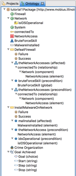
Now that we have defined a package, we can begin adding components, relationships, and modeling elements. We will define three component classes and one relationship.
- Right click the package you defined before and select Add Component.
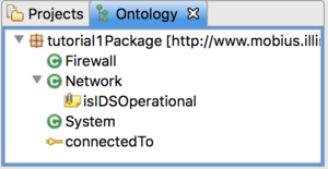
- Change the name to System.
- Click the File -> Save menu item to save the System component.
- Add two more components called Network and Firewall, but don't save them yet. Networks and firewalls are both types of systems. In our ontology, we can define that inheritance relationship by specifying System as a parent of Network and Firewall.
- Bring the Network component editor tab to the top.
- Next to the Parents list, click the Edit button.
- Double click the System component in the left pane to select it and click Finish.
- Repeat the process in the Firewall component editor.
- When done, right click one of the editor tabs and select Close All.
- When prompted, save all.
- Attributes allow you to specify properties about a component. We would like to specify whether or not a network has an IDS currently monitoring it.
- Right click the Network component and select Add Attribute.
- Change the name to, isIDSOperational.
- Change the type to Boolean.
- Change the default value to true.
- Save and close the attribute editor.
- Notice that our package now contains three component classes. Next, let's create a relationship.
- Right click the package and select Add Relationship.
- Change the name to connectedTo.
- Relationships are directional, so when you say that component A is connectedTo component B, that does not mean that B is necessarily connected to A. However, we'd like this relationship to be symmetric, which means that A connectedTo B implies that B connectedTo A. To do this, check the Symmetric checkbox.
- The domain of a relationship defines which types of components this relationship can originate from. We would like to be able to use this relationship to connect Networks, Firewalls, and even Systems together. Relationships leverage the inheritance structure of components, so to accomplish this, we only need to add System to the domain.
- Click the Edit button next to the Domain list.
- Select the System component class from the available list and click the > button to add it to the selected list. Click Finish when done.
- The range of a relationship is similar to the domain, except that it defines what types of components this relationship can connect to. Add System to the range of the relationship.
- Save and close the Relationship.
Adding ADVISE State Variables
We now have everything we need to begin drawing System diagrams containing systems, networks, and firewalls and connected by the connectedTo relationship. However, in order to begin generating useful ADVISE models from our ADVISE Meta model, we must define the underlying elements that will be generated. Let's start with the ADVISE state variables.
- We'd like to define an access element that indicates that the adversary as gained access to a network.
- Right click the package and select Add ADVISE Element -> Access.
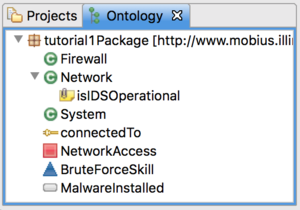
- Change the name to NetworkAccess.
- We also need an SystemSV that indicates that an adversary has installed malware on a Network.
- Right click the package and select Add ADVISE Element -> System State Variable.
- Change the name to MalwareInstalled.
- Change the type to Boolean.
- Change the value to false. This indicates that this state variable will start out with an initial value of false.
- Save all open editors.
- We want the generator to create instances of NetworkAccess and MalwareInstalled for every network that we define in our system diagram. To do this, we need to reopen the Network component and indicate that these state variables are dependent elements of the Network component.
- Double click the Network component to open its editor.
- In the Dependents section, use the Edit button to add the two state variables.
- Save and close all editors.
- Finally, we want to add a skill that defines how effective the adversary is at brute force attacks.
- Right click the package and select Add ADVISE Element -> Skill.
- Change the name to BruteForceSkill.
- Very often with skills, we don't want to create instances that are associated with individual components in our system diagram, but rather a single instance that is used throughout. In other words, an adversary doesn't have a BruteForceSkill for each individual network in our system, but rather a single skill of that type that defines how skilled he is in a behavior. To accomplish this, we need to make this a global element. When an ADVISE model is generated, a single instance of each global element is also generated regardless of what system is defined by the diagram.
- Click the Global check box.
- Save and close all editors.
Adding ADVISE Attack Steps
We have defined the elements that will give our generated ADVISE models state. We now need to define attack steps that will change the model's state. There are a lot of similarities between attack steps in ADVISE and the attack step classes we will define in the ontology. If you aren't familiar with ADVISE attack steps, please review the documentation before proceeding.
- Let's create an attack step that installs malware on a network.
- Right click the package and select Add ADVISE Element -> Attack Step.
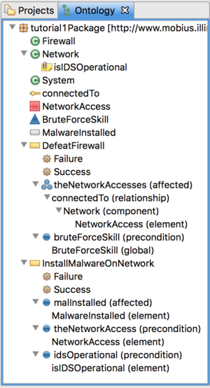
- Change the name to InstallMalwareOnNetwork.
- Save the attack step.
- Open the Network component and add InstallMalwareOnNetwork to the list of dependent elements. Now when a network is defined in the system diagram, an InstallMalwareOnNetwork attack step for that network will be generated in the ADVISE model.
- The next few fields are similar to what you'd find in an ADVISE model, so we won't go into depth on each one.
- Set the cost expression to return 10;
- Set the timing distribution to an exponential with rate return 0.5;.
- Set the precondition expression to return ${theNetworkAccess};
- Save the attack step.
- The next few fields are similar to what you'd find in an ADVISE model, so we won't go into depth on each one.
- Everything you have done in this section until now should look familiar except the precondition expression above. Unlike the other expressions, this is not valid C++ code. Instead it include a macro variable called theNetworkAccess. The entire string ${theNetworkAccess} will be replaced at generation time with the appropriate ADVISE element. However, we must specify in the ontology how to do that replacement using a Precondition Element.
- Right click the InstallMalwareOnNetwork attack step and select Add Precondition -> Element.
- Change the label to theNetworkAccess. Notice that this is the same string as the inside of the macro variable from the code expression we wrote earlier. Attack steps can have many precondition elements and this identifies which element the macro is referring to.
- Now we need to give the generator instructions on how to find the correct ADVISE element to insert into the code expression in place of the macro variable. We do this by creating a path from the attack step's defining component (a Network component). The path for the precondition element is a very simple one, but we will create a more complex one soon.
- Right click theNetworkAccess precondition element and select Add Path Condition -> Element'. This tells the generator to look for an ADVISE element that is a dependent of the Network component (the defining component of this attack step).
- In the editor, change Dependent Element to NetworkAccess.
- Save and close all editors.
We've created an attack step and used a precondition element to tell the generator that when it sees ${theNetworkAccess} in code expressions, it should find the NetworkAccess associated with the attack step's defining network and put that element's name in the code instead. We need to finish defining the InstallMalwareOnNetwork attack step by defining a set of outcomes for the attack step.
- Create a failure outcome on the InstallMalwareOnNetwork attack step.
- Right click the InstallMalwareOnNetwork attack step and select Add Outcome.
- Change the name to Failure.
- Change the outcome probability to return 0.1;.
- Change the detection probability to if(${idsOperational}) return 0.99; else return 0.2;.
- Leave the effects expression blank.
- Create a success outcome on the InstallMalwareOnNetwork attack step.
- Change the name to Success.
- Change the outcome probability to return 0.9;.
- Change the detection probability to if(${idsOperational}) return 0.6; else return 0.1;.
- Change the effects expression to ${malInstalled} = 1;
- Create a precondition element on the attack step that binds to the Network's isIDSOperational attribute.
- Set the precondition element's label to idsOperational.
- Add an element path condition and set the dependent element to Network.isIDSOperational.
- Create an affected element on the attack step similar to how we created a precondition element earlier.
- Set the affected element's label to malInstalled.
- Add an element path condition and select the dependent element to be MalwareInstalled.
We have now fully defined the attack step. Notice that we have added a new precondition element that binds to the network component's isIDSOperational attribute. We use a precondition element because the attack step doesn't modify the value of this attribute, only reads it. In an ADVISE model, the System State Variable that represents the attribute will be connected by and arc that points towards the attack step. We also defined an affected element that binds to the network component's MalwareInstalled system state variable. In the generated ADVISE model, the SSV that indicates whether malware has been installed on the network will be connected to that attack step by an arc that points away from the attack step.
We now have to create a second attack step that will defeat a firewall and allow the adversary to gain network access to all connected networks. We will use an affected collection in this attack step definition that will contain all NetworkAccess elements from any networks connected to the firewall.
- Create the new attack step in the package.
- Change the name to DefeatFirewall.
- Set the cost expression to return 35;.
- Set the timing distribution to an normal distribution with mean
and variance return 10;.
if(${bruteForceSkill} > 600)
	return 20;
else
	return 40;
- Set the precondition expression to
bool oneNotPossessed = false;
bool atleastOnePossessed = false;

for(auto const &n : ${theNetworkAccesses}) {
	if(n->Mark())
		atleastOnePossessed = true;
	else
		oneNotPossessed = true;
}

return atleastOnePossessed && oneNotPossessed;
- Save the attack step.
- Create a new Outcome on DefeatFirewall called Success.
- Set the outcome probability to return 0.3;.
- Set the detection probability to return 0.05;.
- Set the effects to
for (auto const &n : ${theNetworkAccesses})
	n->Mark() = 1;
- Save the outcome.
- Create a new Outcome on DefeatFirewall called Failure.
- Set the outcome probability to return 0.7;.
- Set the detection probability to return 0.4;.
- Save the outcome.
- Add an affected collection to the attack step called theNetworkAccesses.
- Add a relationship path condition to the affected collection and select the connectedTo relationship.
- Add a component path condition to the relationship path condition and select the Network component.
- Add an element path condition to the component path condition and select the NetworkAccess element.
- Add a precondition element to the attack step called bruteForceSkill.
- Add a global path condition to the precondition element and select the BruteForceSkill global element.
- Save and close all editors.
- Open the Firewall component and add DefeatFirewall to the list of dependent elements.
- Save and close all editors.
Adding an ADVISE Adversary
We now must define at least one adversary profile template. We will create an adversary called Criminal Organization and specify the default parameter values.
- Right click on the package and add a new Adversary (Add ADVISE Element -> Adversary).
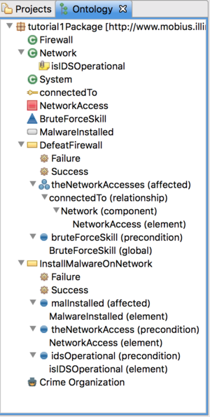
- Change the name to Criminal Organization.
- Change the planning horizon to 3.
- Change the cost, detection, and payoff preference weights to 0.2, 0.05, and 0.75 respectively.
- In the skills section, add the BruteForceSkill.
- Click the Add... button.
- Double click the BruteForceSkill in the left pane to select it.
- In the right pane, click the default initial value for the skill to edit it. Change the value to 700.
- Click Finish.
- Save and close the adversary.
Adding a Metric
We will now define a metric.
- Right click on the package and add a new Metric (Add ADVISE Element -> Metric).
- Change the Name to Goal Achieved.
- Change the Expression to return ${Goal};.
- Change the First Instant to ${Start}.
- Change the Upper Bound to ${Stop}.
- Change the Step Size to ${Step}.
- Save and close the metric.
We have to define User Input elements for each of the macro labels we used above. For Goal, we want the user to select one of the goals that were created in the meta model.
- Right click on the Goal Achieved metric and select Add User Input... -> Choice.
- Change the Label to Goal.
- Change the Field Name to Goal.
- Change the User Instructions to Enter the goal you wish to observe..
- In the class restrictions section, check the box next to Goal.
When the user creates a new instance of this metric in their meta model, they will be prompted using the information you just provided. The will be asked to choose among all Goals defined in the Meta Model. Next, we need to create user inputs for the three parts of the incremental time range.
- Right click on the Goal Achieved metric and select Add User Input... -> String.
- Change the Label to Start.
- Change the Field Name to First Observation.
- Change the User Instructions to Enter the first observation time point..
- Create another User Input String with Label Stop, Field Name Upper Bound, and User Instructions Enter the upper bound on observation times..
- Create another User Input String with Label Step, Field Name Step Size, and User Instructions Enter the length of time between observations..
- Save and close all ontology editors.
We have now completed our ontology. We've added three component types, one attribute, one relationship, three state variables (really four when you count the component attribute) and two attack steps. We have also added an adversary template and a metric. We are now ready to start building ADVISE Meta models!
Defining an ADVISE Meta Model
By this point, you should have an ontology fully defined from the previous tutorial. However, if you'd like to skip the ontology development section, you can download and import this complete ontology package that we will use in this example going forward.
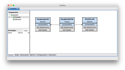
Let's build a small system with two networks, SCADA and Corporate. The two networks will both have a single firewall, which joins the two.
Starting up Mobius and Creating a New ADVISE Meta Model
- Launch the Mobius ADVISE Meta Alpha Tool.
- Right click the Open Projects folder and select New Project.
- Name the project Tutorial1.
- Right click on the Tutorial1 project folder and select New.
- Select Atomic in the bottom pane and click Next.
- Select the Advise Meta Model from the list, enter the name twoNets, and click Finish.
- Select the File -> Save menu item.
Adding Components and Relationships to the Diagram
- In the components tree on the left, expand the System component node to make the Firewall and Network component types visible.
- Add a Network component called CorporateLAN
- Drag and drop a Network component on to the diagram.
- Click on the new Network 1 component and select the Edit Details button.
- Change the name to CorporateLAN.
- Set the isIDSOperational attribute to false.
- Click Finish.
- Add a Network component called SCADALAN and leave the isIDSOperational attribute set to true.
- Add a Firewall and name it CorpSCADAFW.
- Add a new connectedTo relationship from the firewall to the corporate LAN component.
- Select the CorpSCADAFW component, click Add Relationship, and click on the CorporateLAN component.
- Select the connectedTo relationship from the drop down list.
- Click Finish.
- Add a new connectedTo relationship from the firewall to the SCADALAN component.
- Click the File -> Save menu item.
Defining Goals
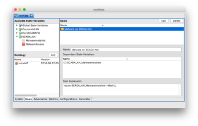
- Select the Goals tab at the bottom of the ADVISE Meta Atomic Model Editor window.
- Select the New Goal 1 goal from the list in the upper right.
- Change the name below to read Malware on SCADA Net
- Add the SCADALAN_MalwareInstalled state variable to the list of state variables
- Expand the SCADALAN component in the Available State Variables tree on the left side of the window.
- Click and drag the MalwareInstalled system state variable.
- Drop it in the list of Dependent State Variables.
- Change the Goal Expression.
- Highlight "false."
- Double click the SCADALAN_MalwareInstalled state variable in the Dependent State Variable list above.
- Note that "->Mark()" was automatically appended onto the state variable name. If you type the name yourself, don't forget to add the "->Mark()", without the quotes, or the code will not compile.
- Click the File -> Save menu item.
Defining Adversaries
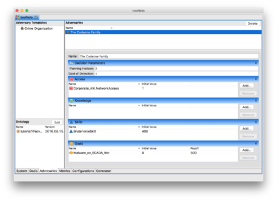
- Select the Adversaries tab at the bottom of the ADVISE Meta Atomic Model Editor window.
- Click and drag the Crime Organization adversary template over to the Adversaries list on the right side.
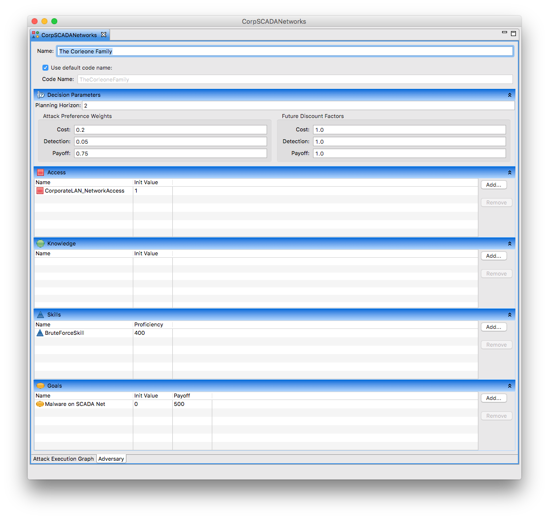
- Change the name below to The Corleone Family.
- Change the planning horizon to 2 and leave the cost of detection the same as what is defined in the template.
- In the Access section, add the CorporateLAN_NetworkAccess
- Click the Add button.
- Select the CorporateLAN_NetworkAccess element in the left pane.
- Click the > button.
- Click Finish.
- In the Skills section, change the Corleone family's BruteForceSkill to 400.
- Click on the initial value column where you see the number 700.
- Enter 400 and hit the enter key.
- In the Goals section, add the Malware on SCADA Net goal.
- Set the payoff to 500.
- Click the File -> Save menu item.
Defining Metrics
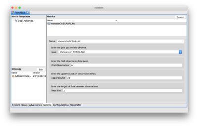
- Click and drag the Goal Achieved metric over to the Metrics table in the upper right corner of the window to create the new metric.
- Change the name to MalwareOnSCADALAN.
- Select the Malware On SCADA Net goal.
- Enter 0 for the First Observation.
- Enter 24 for the Upper Bound.
- Enter 2 for the Step Size.
- Click the File -> Save menu item.
Defining Configurations
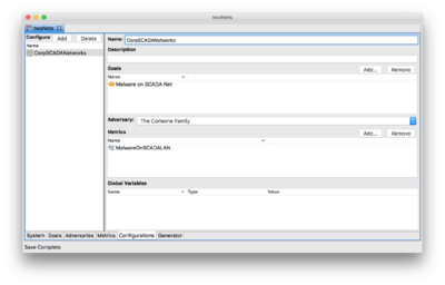
- Select the Configurations tab at the bottom of the ADVISE Meta Atomic Model Editor window.
- Select the New Configuration 1 configuration from the list on the left.
- Change the name on the right side to read CorpSCADANetworks
- Add the goal defined above to the configuration.
- Click the Add button in the Goals section.
- Select the Malware on SCADA Net goal from the list.
- Click Finish.
- Select The Corleone Family as the adversary for this configuration.
- Add the metric defined above to the configuration.
- Click the Add button in the Metrics section.
- Select the MalwareOnSCADALAN metric from the list.
- Click Finish.
- Click the File -> Save menu item.
Generating the ADVISE Model
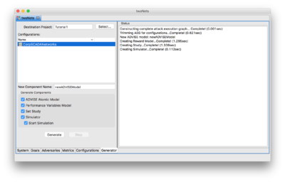
- Select the Generator tab at the bottom of the ADVISE Meta Atomic Model Editor window.
- Select the CorpSCADANetworks configuration from the list on the left.
- Click the Generate button.
- Read the messages on the right and make sure there were no errors.
Once the generation completes, the simulator window should appear and begin executing the simulation. After a brief execution, the results file should be displayed.
Under Construction
The remaining of this tutorial is currently under construction and is using an older version of the tool.
The Generated ADVISE Model
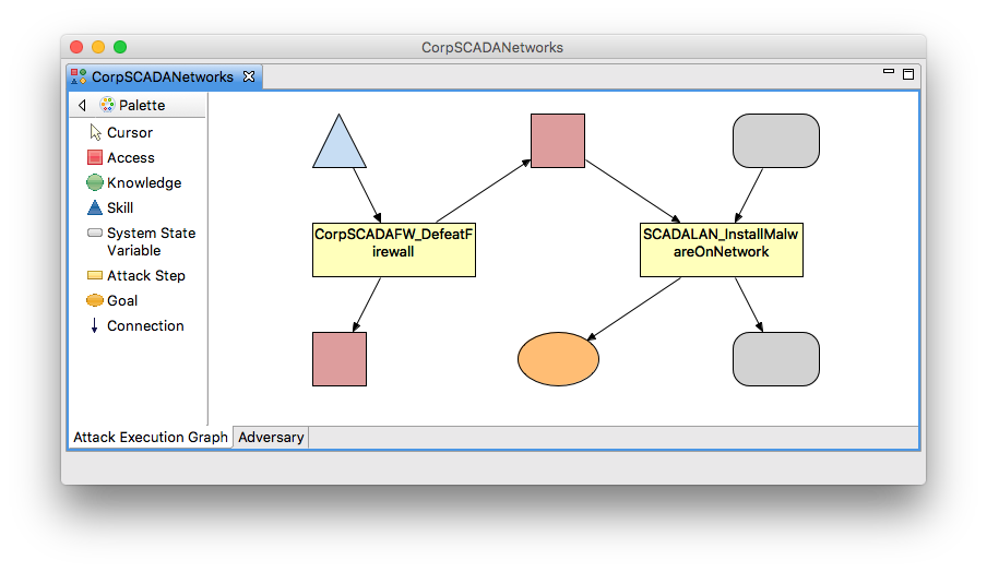
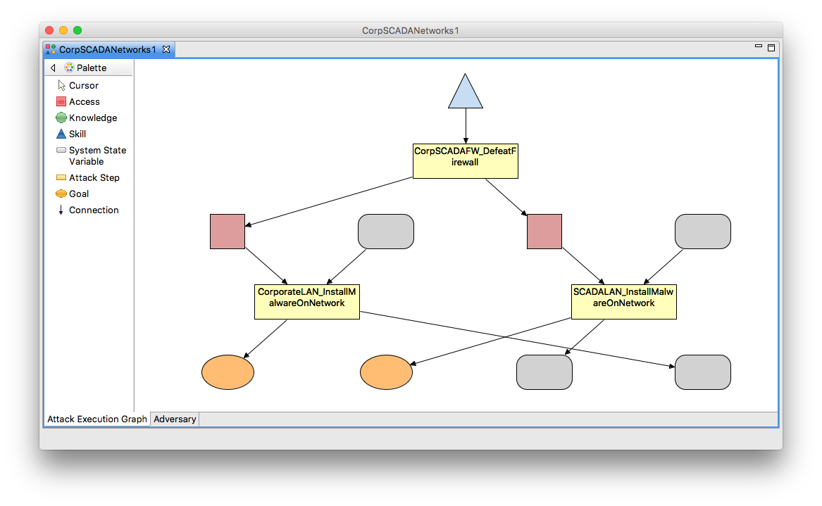
If you look in the Atomic folder of your project, a new ADVISE model called CorpSCADANetworks should now exist. Open that model to see something like the image below. Notice that this doesn't generate a complete ADVISE model based on your system diagram. Instead, it generates a trimmed ADVISE model based on your diagram and the goal definitions in the configuration you generated. For example, the CorporateLAN_InstallMalwareOnNetwork attack step is absent because the only goal we defined does not include that step in any of the possible paths. If you want to see the complete ADVISE model, create a new Goal Definition called Malware on Corporate Net like we did for the SCADA LAN and either add it to your CorpSCADANetworks configuration or create a new configuration that includes both goals.
Defining the Reward Model
Let's create the remaining pieces of this Möbius model. We will be adding two performance variables to report the state of the accesses and another performance variable to report the state of the goal. These steps are done the same way as the normal Möbius distribution, so we'll describe them at a higher level. If you're new to Möbius, please review the Möbius tutorial in the Möbius Manual.
- Right click on the Tutorial1 project and select "New" from the popup menu.
- Select "Reward" from the Component Category and select the "Next >" button at the bottom of the dialog.
- The component type will be "Performance Variable Model". Enter "CorpSCADANetworksRM" in the Component Name field and select "Next >".
- Select "CorpSCADANetworks" and click "Finish".
- Add a new variable called "a_CorporateLAN_NetworkAccess".
- In the "Rate Rewards" tab, define the reward function to be:
return CorpSCADANetworks->CorporateLAN_NetworkAccess->Mark();
- In the "Time" tab, define the timing type to be an "Instant of Time" with an incremental range. The range should be 0-500 with a step size of 10.
- In the "Rate Rewards" tab, define the reward function to be:
- Add a new variable called "a_SCADALAN_NetworkAccess".
- In the "Rate Rewards" tab, define the reward function to be:
return CorpSCADANetworks->SCADALAN_NetworkAccess->Mark();
- In the "Time" tab, define the timing type to be an "Instant of Time" with an incremental range. The range should be 0-500 with a step size of 10.
- In the "Rate Rewards" tab, define the reward function to be:
- Add a new variable called "g_MalwareOnSCADANet".
- In the "Rate Rewards" tab, define the reward function to be:
return CorpSCADANetworks->MalwareOnSCADANet->Mark();
- In the "Time" tab, define the timing type to be an "Instant of Time" with an incremental range. The range should be 0-500 with a step size of 10.
- In the "Rate Rewards" tab, define the reward function to be:
- Save and close the reward model.
You now have a reward model for your ADVISE atomic model that measures the state of each knowledge item and goal at 5-time-unit intervals. This should give you a rough view of how the adversary will progress through the model.
Defining the Study
- Create a new "Range Study" called "CorpSCADANetworksStudy".
- Save and close the study.
Since no global variables are defined in our model, we simply need to create an empty study.
Running the Simulation
- Create a new simulation called "CorpSCADANetworksSim" in the "Solver" folder.
- The Simulator dialog will open automatically.
- The "Simulation Parameters" tab will be shown. The "Build Type" entry will be shown about three-quarters of the way down.
- Click in the list box and select "Normal" as the build type.
- Make sure the "Enable Mobius Trace" check box is selected. We will use the trace information in the next section.
- Click on the "Run Simulation" tab and click the "Start Simulation" button.
- Wait for the simulation to complete; you should now be looking at the "Results" tab.
- Scroll down to see the mean values of the three reward variables at the various time points.
- Values should be similar to these results.
From the results, you should notice that the a_CorporateLAN_NetworkAccess is 1.0 from the very beginning because the adversary has that access as part of their initial access, and at no point during the execution do they lose that access.
The a_SCADALAN_NetworkAccess, on the other hand, is only achieved after a successful outcome of the defeat firewall attack step. The execution of the defeat firewall attack step is controlled by the precondition for having access to either the SCADA LAN or the Corporate LAN and the attack step timing distribution. Access to the Corporate LAN is given in this case. The defeat firewall attack step timing distribution is a normal distribution with a mean of 40 in this case and a variance of 10. Therefore, at the start, there is a very low probability that the attack step will be attempted. At time step 40, the mean of the distribution, the probability of attempting the attack step is 50%, however, the probability of success is only 30%. Combining the two we should expect the probability of achieving access to the SCADA LAN to be around 15%. The 14.48% shown in the results is inline with what we would expect. The a_SCADALAN_NetworkAccess continues the trend towards one because once the access is achieved, it is not taken away in this model.
The goal of installing malware on the SCADA LAN, g_MalwareOnSCADANet, is dependent on achieving access to the SCADA LAN. As a result, the "SCADALAN_InstallMalwareOnNetwork" attack step can not be attempted until the defeat firewall attack step succeeds. Once access to the SCADA LAN has been achieved, the probability of successfully installing malware on the SCADA LAN is very high at 90%. As a result, achieving the goal of installing malware on the SCADA LAN closely follows the a_SCADALAN_NetworkAccess results.
Download the archived version of this project.
Viewing Attack path
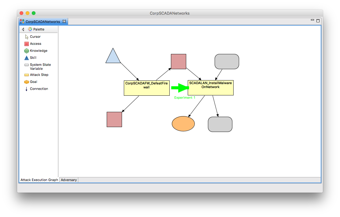
One of the features that has been added to this version of Mobius is the ability to visualize the adversary's path through the ADVISE attack execution graph, AEG. In this tutorial, the ADVISE atomic model is call CorpSCADANetworks.
- Reopen the CorpSCADANetworks ADVISE atomic model.
- In the View menu, select the "Show Results" item. Note: if "Show Results" is already checked, select "Clear" and then reselect "Show Results". This is an issue we are currently working on.
- Mobius will scan the solver directory looking for trace files. Note: if no trace files are found, I dialog box will popup asking you to rerun the simulator with the Mobius Trace File option selected.
- After the processing of the trace files, the attack path will be drawn on the AEG.
